Laser-enhanced visual simultaneous localization and mapping (SLAM) for mobile devices

a technology of simultaneous localization and laser, applied in the field of laser-enhanced visual simultaneous localization and mapping (slam) for mobile devices, can solve the problems of difficult to solve, easy loss of slam algorithms, and inability to recover large flat areas (e.g., texture-less) areas, so as to improve the accuracy and robustness of camera localization and density of environment mapping

Inactive Publication Date: 2017-12-28
ISEE INC
View PDF8 Cites 42 Cited by
  • Summary
  • Abstract
  • Description
  • Claims
  • Application Information

AI Technical Summary

Benefits of technology

[0004]Examples of the disclosure are directed to laser-enhanced visual SLAM solutions, which use a laser line generator with accurate 3D measurement to enhance the accuracy and robustness of camera localization and at the same time the density of the environment mapping. Some examples are directed to laser-enhanced scanning of an object in three dimensions, as well as tracking (e.g., in six degrees of freedom (DOF)) the position and / or orientation of a camera. In some examples, a SLAM device / system of the disclosure, which can include one or more cameras and one or more laser line generators, can scan an object in three dimensions using a laser line while having the ability to move freely with respect to the object, and without requiring analysis and / or capture of a reference image for calibrating or registering the SLAM device.

Problems solved by technology

However, visual SLAM suffers from three main drawbacks: 1) the visual SLAM algorithm can only produce a sparse point cloud of feature points—as such, even recent development of direct SLAM algorithms may fail to recover large flat (e.g., texture-less) areas, such as white walls; 2) the recovered 3D map of the environment does not have an absolute scale of the world; and 3) the SLAM algorithms are fragile and easy to lose when there are few features presented in the image frames.
However, such solutions are often expensive, have high power consumption, and large size.
The standard Kinectfusion type of algorithms require high-end GPUs and a large memory space for storing the volumetric data, which is not affordable for current embedded devices.

Method used


Image

  • Laser-enhanced visual simultaneous localization and mapping (SLAM) for mobile devices
  • Laser-enhanced visual simultaneous localization and mapping (SLAM) for mobile devices
  • Laser-enhanced visual simultaneous localization and mapping (SLAM) for mobile devices

Examples


Embodiment Construction

[0014]In the following description of examples, reference is made to the accompanying drawings which form a part hereof, and in which it is shown by way of illustration specific examples that can be practiced. It is to be understood that other examples can be used and structural changes can be made without departing from the scope of the disclosed examples.

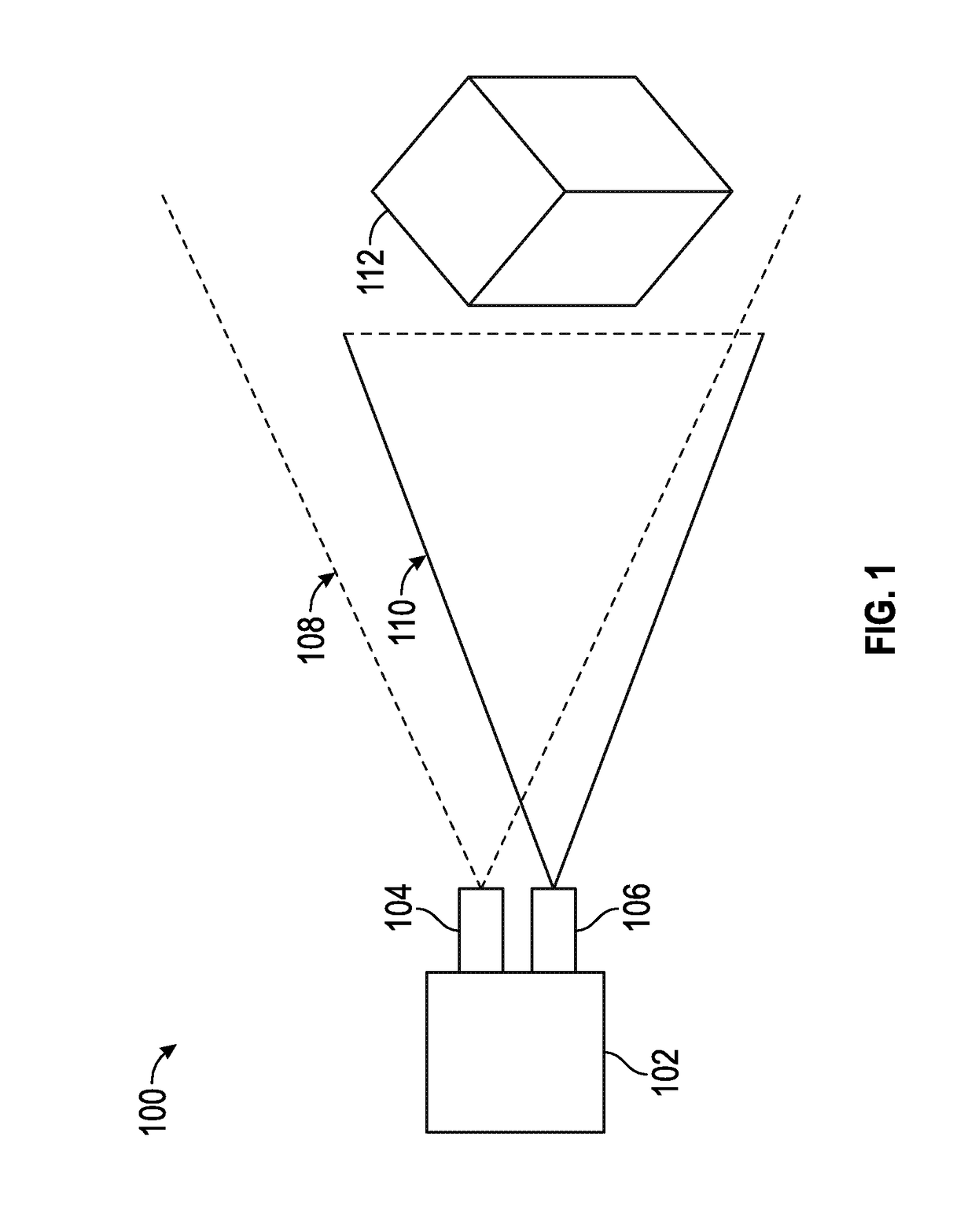
[0015]FIG. 1 illustrates an exemplary laser-enhanced SLAM device configuration 100 according to examples of the disclosure. SLAM device 102 can include an optical camera 104 and a laser line generator 106. Optical camera 104 can be any kind of optical camera, such as an RGB sensor-based optical camera. Laser line generator 106 can be any kind of laser generator that can generate a laser line across an object to be scanned by SLAM device 102, as will be described in more detail below. In some examples, the laser line can be generated by the SLAM device by fanning out a laser beam into a laser plane using an appropriate lens (such a...


PUM


Abstract

Laser-enhanced visual simultaneous localization and mapping (SLAM) is disclosed. A laser line is generated, the laser line being incident on an object and/or environment. While the laser line is incident on the object, one or more images of the object with the laser line incident on the object are captured. The camera is localized based on one or more characteristics of the laser line incident on the object. In some examples, improved feature localization provided by the laser line provides more accurate camera localization, which, in turn, improves the accuracy of the stitched mesh of the object/environment. As such, the examples of the disclosure provide for improved camera localization and improved three-dimensional mapping.

Description

FIELD OF THE DISCLOSURE[0001]This relates generally to localization of a camera and / or mapping of a 3D environment on a mobile device using a visual SLAM solution that is enhanced using a laser line process.BACKGROUND OF THE DISCLOSURE[0002]Visual simultaneous localization and mapping (SLAM) algorithms enable a mobile device to simultaneously build 3D maps of the world while tracking the location and orientation of a camera. The camera can be hand-held or head-mounted for Virtual Reality (VR) / Augmented Reality (AR) solutions, or mounted on a robot, a drone or a car. The visual SLAM algorithms are solely based on an on-board camera without the need for any external localization device or system; thus, they are also referred to as “inside-out” tracking solutions, which are increasingly popular for VR / AR and robotics applications. However, visual SLAM suffers from three main drawbacks: 1) the visual SLAM algorithm can only produce a sparse point cloud of feature points—as such, even re...

Claims


Application Information

Patent Timeline
Patent Type & Authority Applications(United States)
IPC IPC(8): H04N13/00H04N13/02G01B11/25G02B27/09
CPCH04N13/0022H04N13/0271G06T7/0044H04N2013/0081G01B11/2518G02B27/0955G02B27/0933G06T7/204G06T7/579G06T7/74H04N13/254H04N13/271H04N13/128
Inventor ZHAO, YIBIAO
Owner ISEE INC
Why Eureka
Try Eureka