Hip stem

a hip joint and stem technology, applied in the field of prosthetic implants, can solve the problems of increasing the risk of fat embolism and cardiopulmonary complications, limiting the ability to perform normal activities, and debilitating the hip joint, and achieve the effect of less invasive and cheaper manufacturing

Inactive Publication Date: 2018-01-04
IMPERIAL INNOVATIONS LTD
View PDF39 Cites 13 Cited by
  • Summary
  • Abstract
  • Description
  • Claims
  • Application Information

AI Technical Summary

Benefits of technology

[0070]Shallow stems, such as those where the length of the stem is in the range between 50 mm and 70 mm, may be used in younger patients or in patients who are having a first (primary) hip implant, allowing longer implants/stems to be used as revision implants/stems in the future

Problems solved by technology

In certain traumatic situations and arthritic conditions due to aging, the hip joint can be very debilitating; not only causing pain, but also limiting the ability to perform normal activities.
Cement fixation has certain well-known complications, such as thermal necrosis of the bone, increased risk of fat embolism and cardiopulmonary complications, particularly in elderly patients (Parvizi et al.
However, sufficient stability cannot be obtained by conventional cementless femoral stem in osteoporotic (OP) femurs, probably because of poor geometric fit of the implant within the bone cavity (Noble et al.
Consequently, a conventional hip stem implanted in OP patients is prone to movement relative to the host bone while loaded during physiological activity, causing pain and discomfort.
This leads to inhibition of use of the lower limb, deteriorating the quality of the patient's life.
Moreover, conventional stem designs can cause distal load transfer at the tip, the risk of intra-operative femoral fractures, and occurrence of thigh pain.
However, rotational motion of the stem induced by the twist may lead to the formation of a gap at the implant-bone interface.
This high hoop stress may make the thin cortical wall susceptible to fracture in osteoporotic patients (Abdul-Kadir et al.
A small misalignment of the component within the canal may further aggravate the risk of fracture.
Although this can be treated intra-operatively with circlage-wire, the p

Method used


Image

  • Hip stem
  • Hip stem
  • Hip stem

Examples


Embodiment Construction

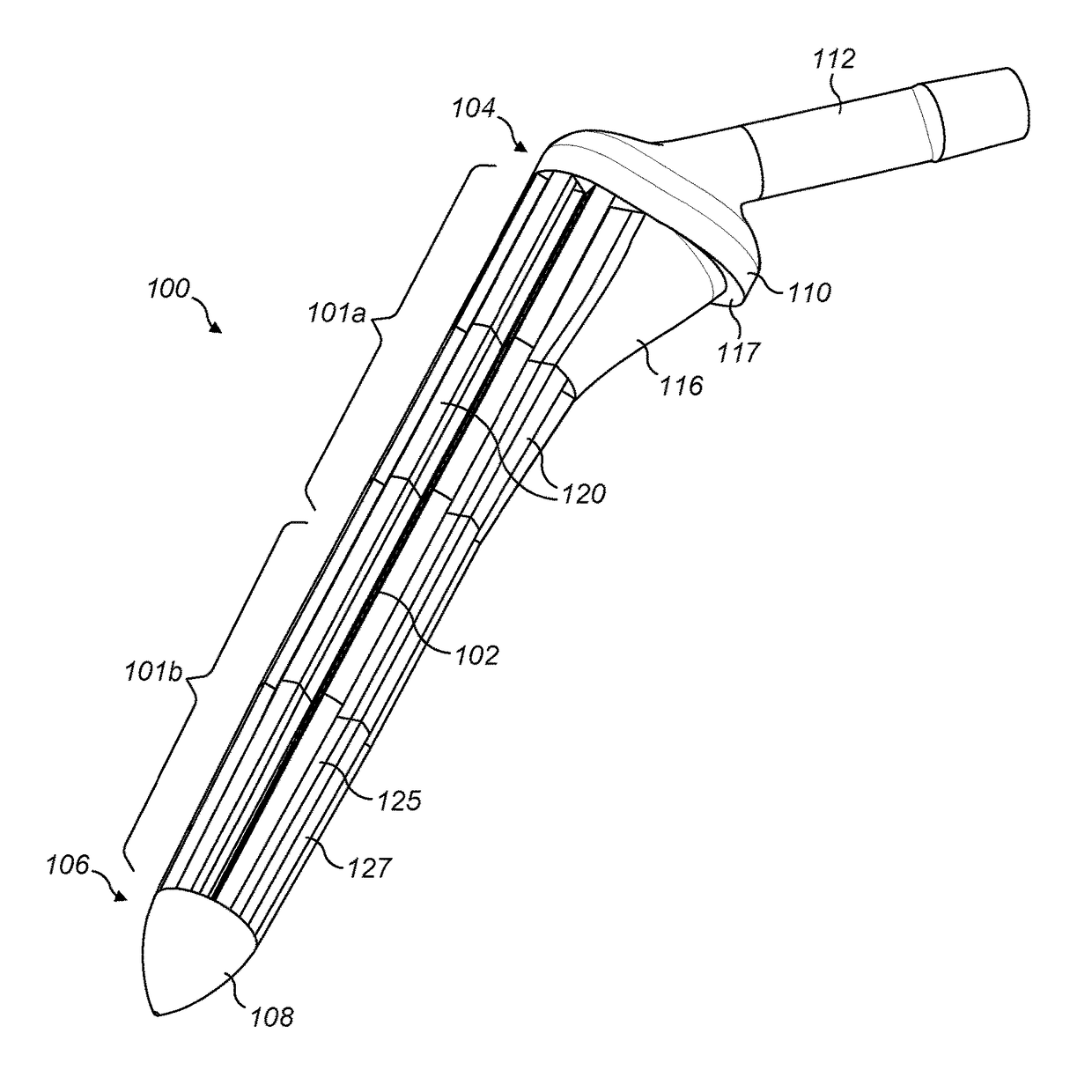
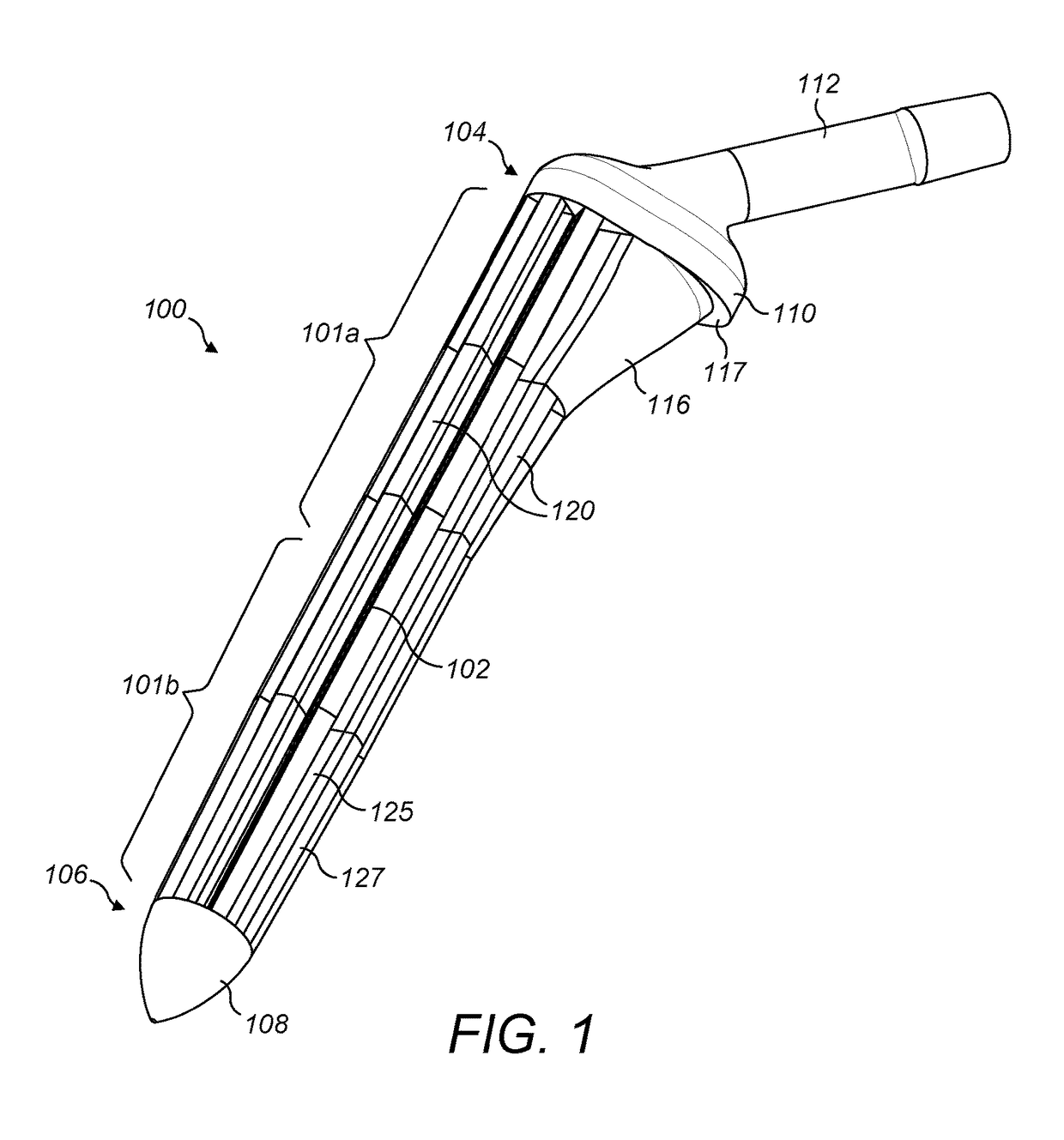
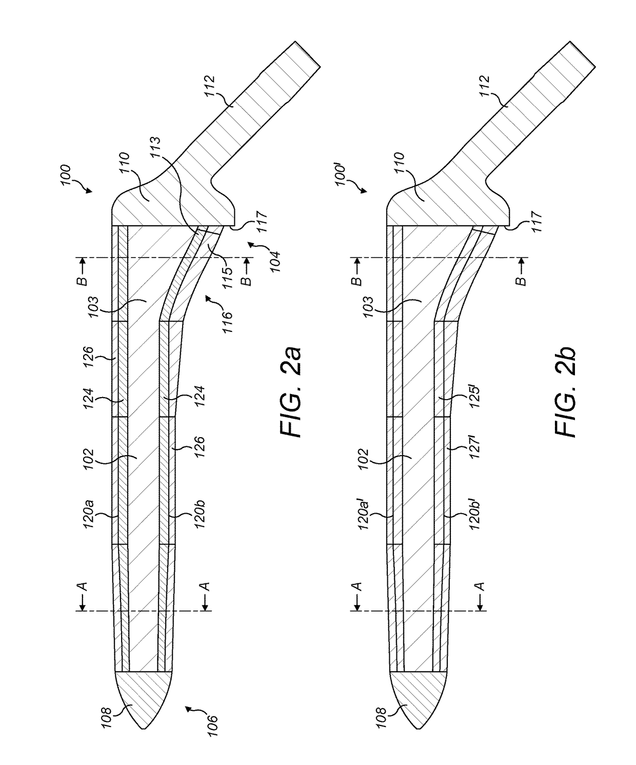
[0090]FIGS. 1 and 2a, 3a and 4b illustrate a first exemplary hip stem 100. The hip stem 100 comprises a central core 102 extending longitudinally within the stem from a proximal end 104 to a distal end 106. A tip 108 is located at the distal end 106 and a collar 110 is located at the proximal end 104. An attachment portion 112 extends from the collar 110 at the proximal end 104 of the stem 100 at an angle of approximately 45 degrees from a longitudinal axis of the stem in the medial direction, for the attachment thereto of a femoral head component (not shown), as known in the art. A thickened proximal medial portion 116 is located towards the proximal end 104, forming a buttress connecting the collar 110 with the main part of the stem for supporting load transfer to the proximal medial wall of the femur when the stem is located in situ within a patient's femoral canal. A lip 117 may be formed between a peripheral edge of the proximal end of the thickened proximal medial portion 116 ...


PUM


Abstract

A stem (100) for use in a joint prosthesis, such as a femoral stem for a hip joint prosthesis, the stem comprising: a solid central core (102); a proximal outer layer (127) disposed over a proximal portion (101a) of the central core, wherein the proximal outer layer comprises a set of longitudinal ribs (120), defining slots (130) there between; and a distal outer layer made of a deformable porous material disposed over a distal portion (101b) of the central core. The arrangement is such that the stem (100) can be made with a relatively large diameter yet without being excessively stiff, for cementless fixation in osteoporotic patients. The deformability of the distal outer layer also mitigates against the risk of intraoperative bone fractures.

Description

FIELD OF THE INVENTION[0001]The present invention relates generally, but not exclusively, to prosthetic implants, particularly to implants used in joint replacement orthopaedic surgery, and more particularly to femoral stems used in hip replacement orthopaedic surgery.BACKGROUND TO THE INVENTION[0002]The hip joint forms the connection between the femur and the pelvis. It consists of two main parts: a ball (femoral head) at the top of the femur (thighbone) that articulates into a round socket (acetabulum) in the pelvis (hipbone), resembling a ball-and-socket joint. The bone surfaces of the ball and socket have a smooth durable cover of articular cartilage that cushions the ends of the bones and enables them to articulate easily without damage. In a healthy hip, a smooth tissue called synovial membrane makes a small amount of fluid that lubricates and almost eliminates friction in the hip joint. The femur consists of a central cylindrical shaft, called the diaphysis and two wider and ...

Claims


Application Information

Patent Timeline
IPC IPC(8): A61F2/36A61F2/30A61F2/28
CPCA61F2/3676A61F2/3672A61F2/30942A61F2002/30013A61F2002/30014A61F2002/30072A61F2002/30879A61F2002/2817A61F2002/30769A61F2002/3668A61F2002/3631A61F2002/30112A61F2002/30919A61F2/30907A61F2/3662A61F2002/30011A61F2002/30884A61F2002/3092A61F2002/30962A61F2002/3694
Inventor AMIS, ANDREWPAL, BIDYUT
Owner IMPERIAL INNOVATIONS LTD
Why Eureka
Try Eureka