Evaporation device

a technology of evaporation device and agitation vessel, which is applied in the direction of evaporation, vacuum distillation separation, separation process, etc., can solve the problems of deformation or deterioration of rollers or wipers, which are in contact with the inner wall, and achieve the effect of efficient evaporation and avoiding the possibility of a part within the agitation vessel arising

Active Publication Date: 2018-01-18
KANSAI CHEM ENG CO LTD
View PDF6 Cites 7 Cited by
  • Summary
  • Abstract
  • Description
  • Claims
  • Application Information

AI Technical Summary

Benefits of technology

[0035]According to the present invention, the volatile component can be efficiently evaporated from the raw material liquid without using a part such as a roller or a wiper. Thus, an even more concentrated

Problems solved by technology

Another matter is that, in the case where the evaporation device is to be stopped, since the temperature of the inner wall is higher than the liquid temperature, if the s

Method used


Image

  • Evaporation device
  • Evaporation device
  • Evaporation device

Examples


Embodiment Construction

[0054]An evaporation device of the present invention will be described with reference to the accompanying drawings.

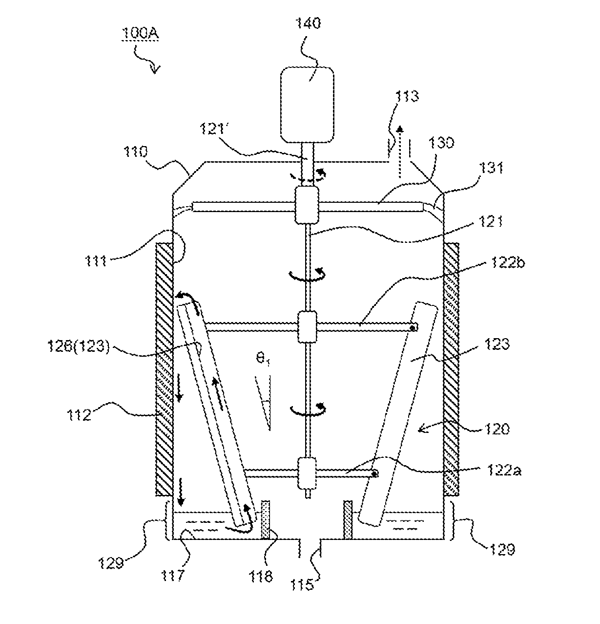
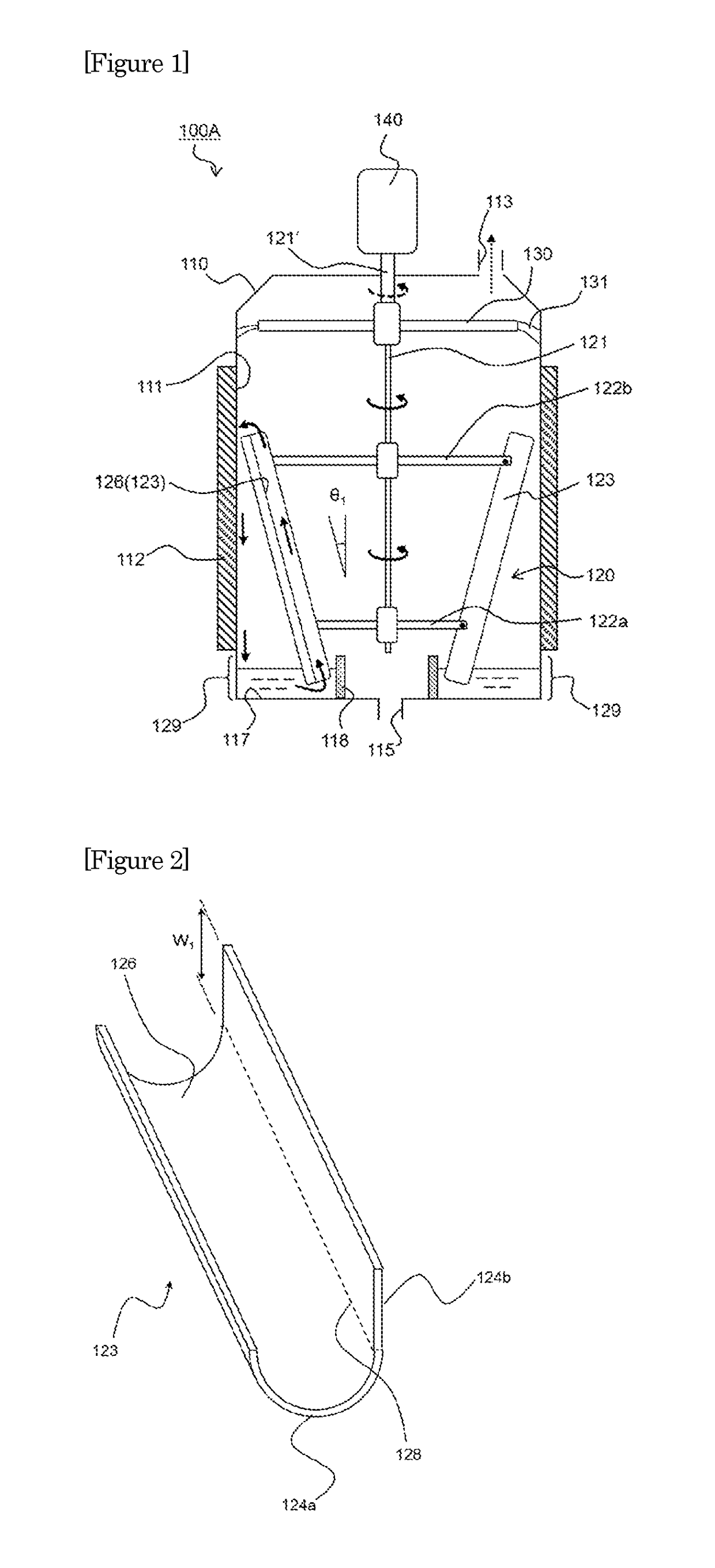
[0055]FIG. 1 is a schematic diagram showing an example of the evaporation device of the present invention. An evaporation device 100A in FIG. 1 includes an agitation vessel 110 to which a raw material liquid is supplied, a jacket 112 that heats an inner wall 111 of the agitation vessel 110, and a liquid-distributing portion 120 that is provided within the agitation vessel 110 and that causes the raw material liquid to flow down the inner wall 111 of the agitation vessel 110.

[0056]The agitation vessel 110 is a hermetically sealable vessel which has a volatile component outlet 113 and a concentrate outlet 115 and in which a liquid, such as an aqueous solution or slurry, can be received and agitated. In FIG. 1, the volatile component outlet 113 is provided in a top portion of the agitation vessel 110, and a volatile component obtained by evaporation of a constituent compon...


PUM

PropertyMeasurementUnit
Angleaaaaaaaaaa

Abstract

An evaporation device including an agitation vessel to which raw material liquid is supplied. The agitation vessel has a volatile component outlet and a concentrate outlet, a jacket provided on an outer circumference and configured to heat an inner wall, and a liquid-distributing portion configured to cause the raw material liquid to flow down the inner wall. The agitation vessel includes storage portion surrounded by a bottom, the inner wall, and a partition wall portion configured to temporarily store the raw material liquid that flows down, the liquid-distributing portion is constituted by a rotating shaft and at least one channel part having a flow passage which, as the rotating shaft rotates, the raw material liquid temporarily stored in the storage portion flows upward from a lower side of the agitation vessel. The channel part is mounted to the rotating shaft, and the concentrate outlet is provided in the bottom.

Description

TECHNICAL FIELD[0001]The present invention relates to an evaporation device, and more specifically relates to an evaporation device with which solvent recovery from and concentration of a liquid can be efficiently performed.BACKGROUND ART[0002]In the food industry and the chemical industry fields, for example, a type of evaporation device called “falling film evaporation device” is used to recover a solvent from a liquid containing foreign substances and impurities or to concentrate the liquid.[0003]FIG. 16 is a diagram schematically showing an evaporation system including a conventional falling film evaporation device.[0004]An evaporation system 900 includes a raw material tank 910 containing a raw material liquid serving as a raw material, a falling film evaporation device 800, a vacuum pump 920, and a condenser 930. The raw material liquid is caused to flow from the raw material tank 910 to a preheater 906 through a conduit 904 by driving of the pump 902, temporarily preheated in...

Claims


Application Information

Patent Timeline
IPC IPC(8): B01D1/22B01D5/00B01F7/18B01F15/06
CPCB01D5/006B01F2015/062B01D1/223B01F7/18B01F15/06B01D1/0088B01D1/305B01D3/008B01D3/10B01D1/0064B01D1/22B01D5/00B01F27/80B01F35/71B01F35/90B01F27/90B01F2035/99
Inventor MUKAIDA, TADAHIROYAMAJI, HIROSHINODA, HIDEO
Owner KANSAI CHEM ENG CO LTD
Why Eureka
Try Eureka