Heat exchanger with thermal fluid-containing shaft and shaft-riding auger for solids and slurries

a technology of heat exchanger and shaft, which is applied in the direction of lighting and heating apparatus, dryers with progressive movement, furnaces, etc., can solve the problems of large surface area large surface area achieved at a penalty in overall size and cost, and large surface area achieved at a small volume , the effect of increasing the rotation ra

Inactive Publication Date: 2018-01-18
WHITNEY JOHN POTEE +2
View PDF16 Cites 7 Cited by
  • Summary
  • Abstract
  • Description
  • Claims
  • Application Information

AI Technical Summary

Benefits of technology

[0012]The inventors wished to provide a heat exchanger-processor which boosts efficiency by optimizing residence time in each of a plurality of serially arranged transport segments and by self-cleaning during operation. Additionally, the inventors sought to provide such an exchanger-processor which would be inexpensive, lacking complex and costly rotary junctions, and which would be easily maintainable, its pipes being adjustable and its pipes and augers being replaceable without welding or other complicated and costly work.
[0029]The present invention provides the large surface area in a small volume. Use of these methods and apparatus provide utility by allowing a waste heat stream to supply the energy typically required to dry materials. Utility for a fuel driven system is a consequence of its efficient heat transfer. An exemplary embodiment of the heat exchanger in accordance with the present invention provides apparatus for economically continuously thermally processing a solid using an organic vapor or steam (or other thermal fluid such as, for example, a molten salt) as a heating medium for a heat exchange surfaces of a plurality of fixed pipes without any need for rotary unions. A rotating spiral (also referred to herein as a flight or as an auger flight) on the outside of the pipe conveys the process material longitudinally over the surface of each heat exchange pipe. The pipes are of smaller diameter than is typical of shafted thermal screws, allowing the spiral conveyors outside the pipes to operate at a higher rate of rotation while maintaining the same peripheral speed (peripheral speed is the speed of the inner portion of the spiral as it rides on the pipe, not the speed of the outer portion of the spiral), resulting in improved mixing and, consequently, an improved U factor without undue wear.
[0030]Also in accordance with the present invention, the heat exchange pipes are easily rotated after they have become worn on one side, so that all four sides can be utilized before the pipes must be replaced. This rotation is accomplished by merely unbolting flanges that hold the pipes in place and turning the pipes.
[0032]Also in accordance with the present invention, such scraping may be accomplished without metal-to-metal contact between scrapers when surfaces passing in mutual close proximity dislodge the adhered or adhering material. Sometimes, as in the case of the conveyance surfaces, it is sufficient to only remove a portion of the adhered material in order to maintain the void to be occupied by moving material. Sometimes, a thin fouling layer remaining on a surface is tolerable after most of the material has been dislodged. Advantageously, minimizing metal-to-metal contact reduces wear on the heat exchanger.
[0033]The material being processed frequently undergoes considerable shrinkage in volume. Advantageously, the exchanger in accordance with the present invention uses multiple heat exchangers arranged in sequence, such that the speed of movement through each heat exchanger can be controlled independently. Thus, as process material shrinks, it can be conveyed more slowly when it enters a exchanger segment which is set at a lower speed. This makes it possible to maintain the level of process material to assure complete cover and contact with the entire heat exchange surface in each segment of the heat exchanger.
[0034]The U factor is improved by higher rotational speed of the spirals (radians per second), resulting in a peripheral speed of at least up to 26 feet per minute. However, many of the materials to be processed are at least somewhat abrasive. Wear on metal parts is understood to be a function of the square of the speed of the movement. In somewhat abrasive duty the wear on screws limits the speed at which they can be rotated with acceptable life to about 19 feet per minute peripheral. This is 2 rpm for 3 inch diameter screws. Because the U factor is improved by higher speed, it is desirable to limit the diameter at which the friction between the pipe and the spiral that rides on it takes place while using more rotational speed to maximize the mixing. The peripheral speed, again, is the speed of the inner portion of the spiral as it rides on the pipe, not the speed of the outer portion of the spiral. Thus, at a given rate of rotation, if the pipe diameter is reduced, this peripheral speed is reduced. Consequently, abrasive wear is reduced.

Problems solved by technology

One such perceived difficulty realtes to steam-heated dryers.
However, the steam commonly available is often at a temperature not much higher than the approximately 100° C. required to evaporate water from common process materials.
If traditional technology is used, large surface area is achieved at a penalty in overall size and cost.
As heat exchange surfaces, both screws and paddles are complex and expensive.
When 150 PSI design is used with a thermal screw, the shape of the flight on the screw is limited when practical materials of construction are used.
The necessary rotary unions are very costly for these temperatures and pressures.
These machines are formed of very complex shapes with very costly heat exchange surfaces.
When steam or organic vapors are used, very complex internal structures are required to remove the condensate from the hollow flight thermal screws.
At such times, it is necessary to scrape the heat exchange surfaces in order to prevent the adherent material from fouling the surfaces so severely that the heat exchange capacity is unacceptably impaired.

Method used


Image

  • Heat exchanger with thermal fluid-containing shaft and shaft-riding auger for solids and slurries
  • Heat exchanger with thermal fluid-containing shaft and shaft-riding auger for solids and slurries
  • Heat exchanger with thermal fluid-containing shaft and shaft-riding auger for solids and slurries

Examples


Embodiment Construction

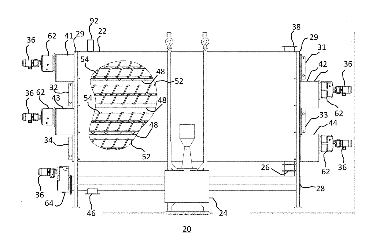
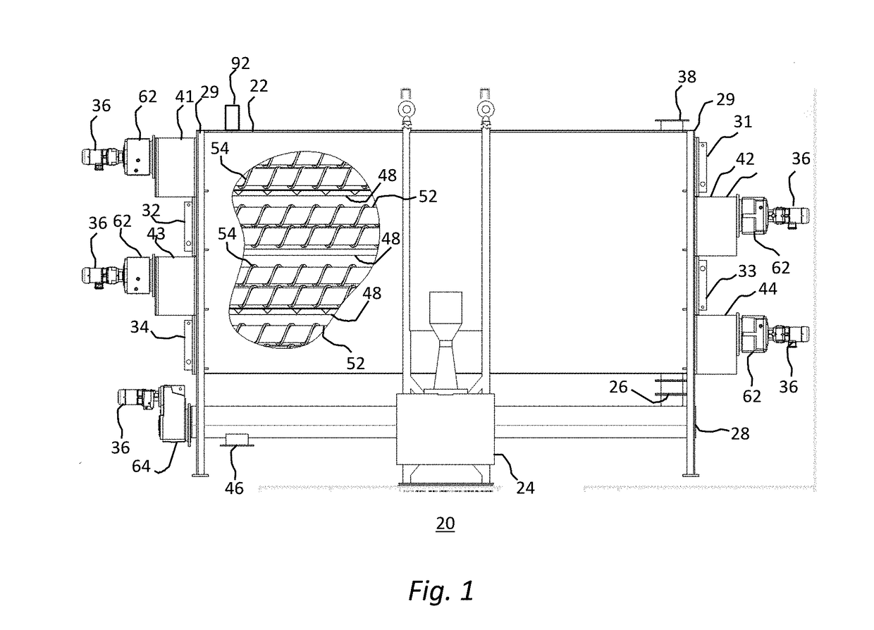
[0055]FIG. 1 shows a side elevational view of a first exemplary embodiment of the heat exchanger in accordance with the present invention, shown generally at 20, having a housing 22, first through fourth steam chests 31, 32, 33, and 34, first through fourth transport systems 41, 42, 43, and 44, a condenser 24, an air lock 26, a discharge system 28, motors 36, a feed material inlet 38, a feed material outlet 46, conveyor drives 62 and discharge drive 64. Partially cut away, this view shows trays 48, pipes 52, and transport augers 54 located inside the housing 22.

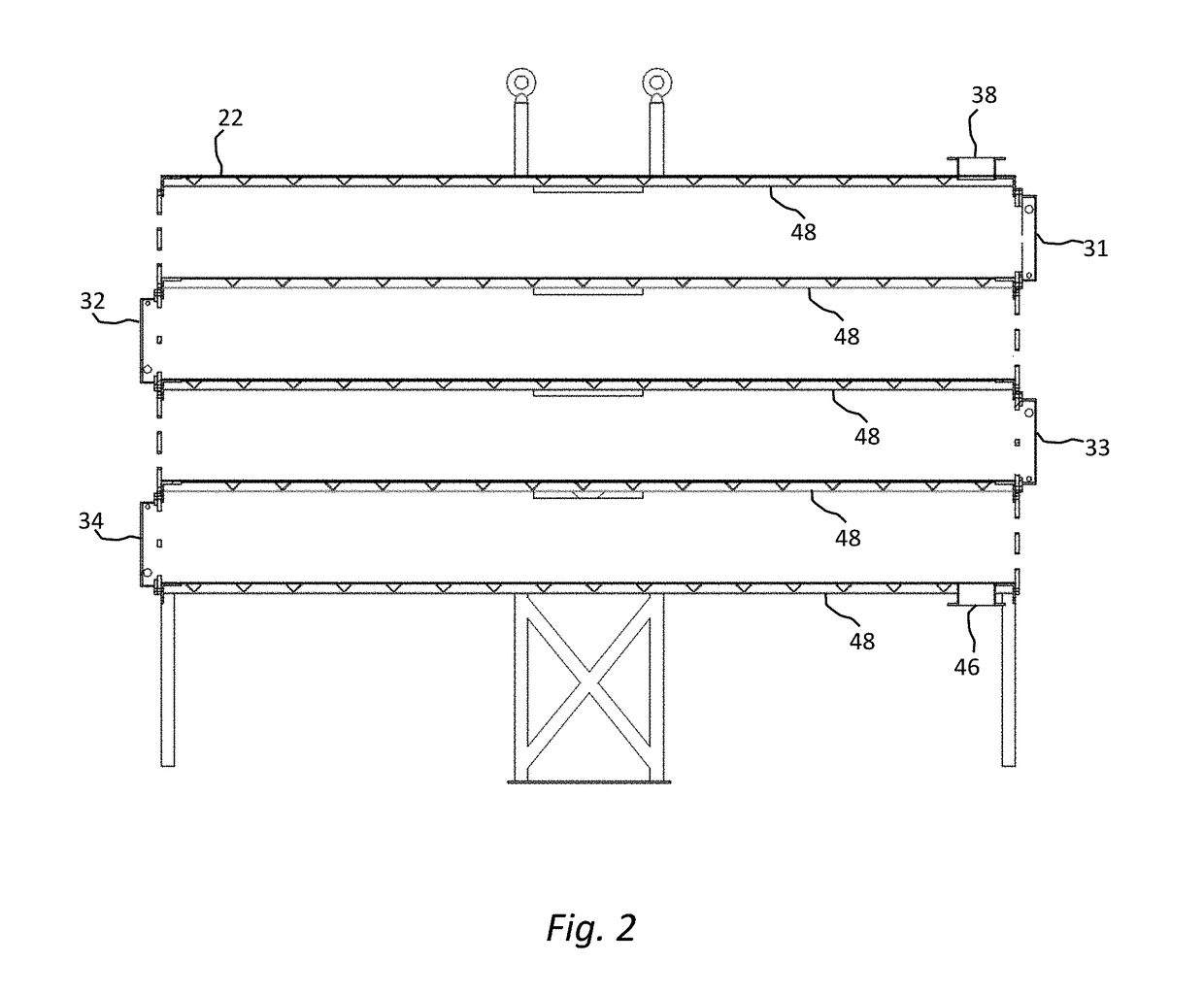
[0056]FIG. 2, a side sectional view of the embodiment of FIG. 1, shows the housing 22, first through fourth steam chests 31, 32, 33, and 34, feed material inlet 38, feed material outlet 46, and trays 48.

[0057]FIG. 3, a perspective view of the embodiment of FIG. 1, shows the housing 22, first and third steam chests 31 and 33, first through fourth transport systems 41, 42, 43, and 44, a condenser 24, an air lock 26, a discharge...


PUM


Abstract

Serially connected heat exchange segments of a heat exchanger are stacked with ends of adjacent segments oriented oppositely. The segments have fixed pipes for heat exchange, pipe-riding shaftless auger flights for conveying feed material, and flanges for low-cost adjustment, removal and replacement of pipes and flights. Flights when arranged in arrays are arranged in pairs of counterrotating oppositely handed mutually cleaning flights. Rotary unions are unnecessary in this exchanger.

Description

TECHNICAL FIELD[0001]This application claims the benefit of prior copending provisional application 62 / 192,000, filed 13 Jul. 2015, the entirety of which is incorporated herein by reference.[0002]The present invention relates to an indirectly heated thermal processor, more particularly to a fluid-heated thermal processor equipped with an auger for conveying material, and especially to such with a shaft-riding auger.[0003]The inventors were intrigued by various difficulties they perceived plaguing apparatus for the thermal processing of materials, as, for example, for the purpose of drying a material. One such perceived difficulty realtes to steam-heated dryers. Medium-to-low pressure steam often is used for drying a material, because it contains a large amount of heat energy and is widely available as a byproduct of industrial processes. However, the steam commonly available is often at a temperature not much higher than the approximately 100° C. required to evaporate water from com...

Claims


Application Information

Patent Timeline
Patent Type & Authority Applications(United States)
IPC IPC(8): F26B3/04F26B21/02F26B21/00F26B25/06F26B15/12
CPCF26B3/04F26B15/12F26B25/06F26B21/02F26B21/005F26B3/20F26B3/22F26B17/20
Inventor WHITNEY, JOHN POTEEWHITNEY, PRESTON OCHASWECHSLER, MARK
Owner WHITNEY JOHN POTEE
Why Eureka
Try Eureka