Wire electrical discharge machine and wire electrical discharge machining method

Inactive Publication Date: 2018-01-25
FANUC LTD
View PDF7 Cites 3 Cited by
  • Summary
  • Abstract
  • Description
  • Claims
  • Application Information

AI Technical Summary

Benefits of technology

[0012]Thus, the position of the workpiece with the corrected position error in the planar direction is calculated by using the position error information indicating the position error in the planar direction in the workpiece after the relative positions between the first guide unit and the second guide unit are changed. Consequently, it is possible to additionally correct the position error in the planar direction in a state where the inclination error in the planar direction is reduced in advance, further enhance a placement error reduction effect and simplify an arrangement operation. Consequently, it is possible to both improve efficiency of the arrangement operation and maintain machine accuracy for placing the workpiece.
[0013]In the wire electrical d

Problems solved by technology

When the above inclination correcting function is used, even though the inner shape is appropriate, a ma

Method used


Image

  • Wire electrical discharge machine and wire electrical discharge machining method
  • Wire electrical discharge machine and wire electrical discharge machining method
  • Wire electrical discharge machine and wire electrical discharge machining method

Examples


Embodiment Construction

[0037]Referring now to the accompanying drawings, the wire electrical discharge machines according to the present invention will be explained in detail by describing preferred embodiments in relation with wire electrical discharge machining methods.

[Overall Structure of Wire Electrical Discharge Machine 10]

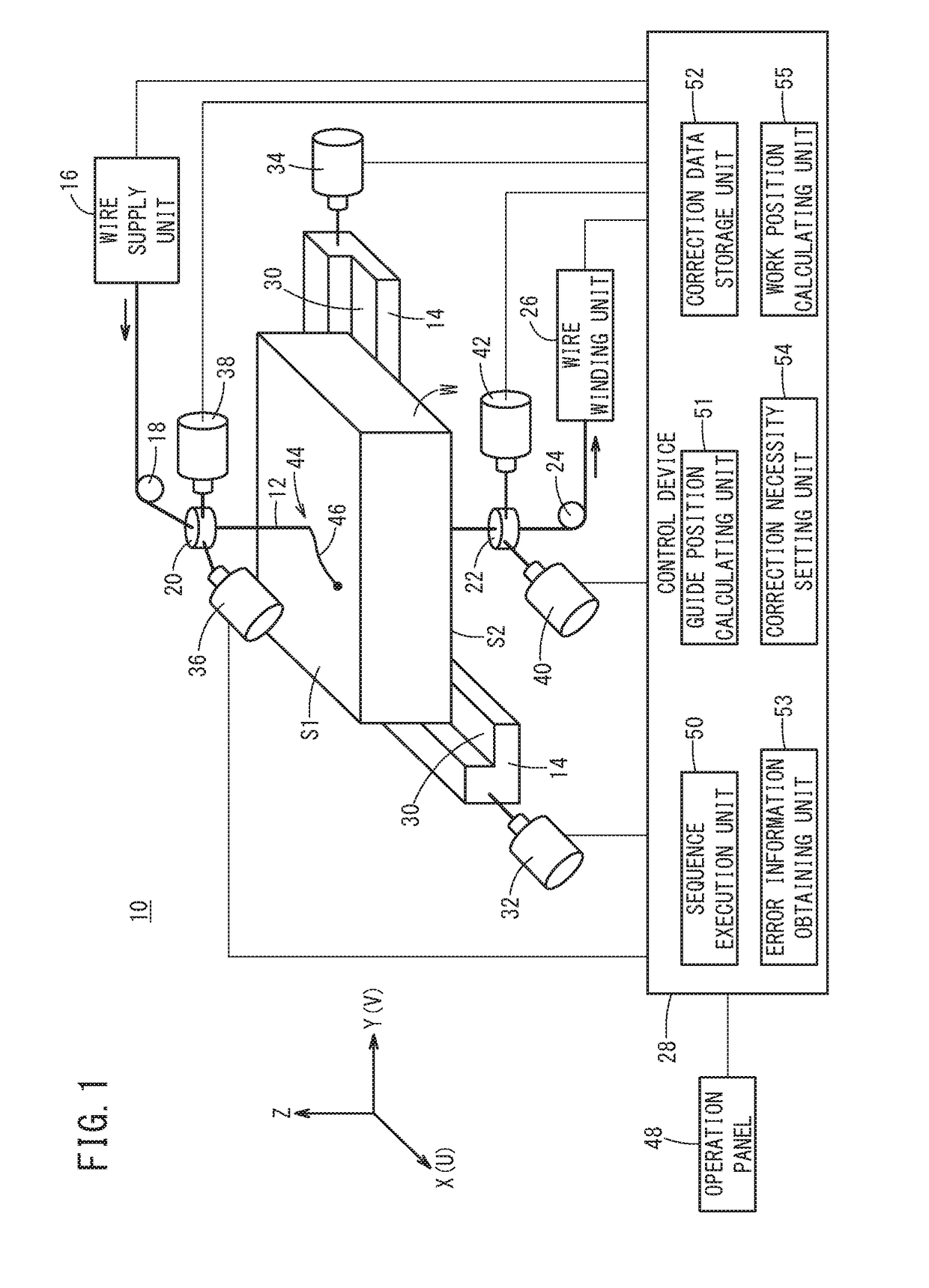
[0038]FIG. 1 is a schematic configuration diagram of a wire electrical discharge machine 10 according to one embodiment of the present invention. The wire electrical discharge machine 10 is a machine tool which operates in accordance with a predetermined machining program and performs electrical discharge machining on a workpiece W by electric discharge generated between a wire electrode 12 and the workpiece W. The wire electrode 12 is formed of, for example, metal material such as tungsten-based, copper alloy-based and brass-based material. On the other hand, the material of the workpiece W is, for example, iron-based material or superhard material.

[0039]The wire electrical disch...


PUM

PropertyMeasurementUnit
Erroraaaaaaaaaa

Abstract

A wire electrical discharge machine obtains position error information indicating a position error in a planar direction in a workpiece placed on a mounting table after relative positions between a first guide unit and a second guide unit are changed, and calculates a position of the workpiece with the corrected position error in the planar direction in a state where a wire electrode is inclined according to an inclined state of the workpiece by using this position error information.

Description

CROSS-REFERENCE TO RELATED APPLICATION[0001]This application is based upon and claims the benefit of priority from Japanese Patent Application No. 2016-145351 filed on Jul. 25, 2016, the contents of which are incorporated herein by reference.BACKGROUND OF THE INVENTIONField of the Invention[0002]The present invention relates to a wire electrical discharge machine and wire electrical discharge machining method for performing electrical discharge machining on a workpiece by generating electric discharge between a wire electrode and the workpiece.Description of the Related Art[0003]Conventionally, there have been developed wire electrical discharge machines that perform electrical discharge machining on a workpiece by generating electric discharge between a wire electrode and the workpiece. In this field, there has been proposed a machining technique that compensates for or corrects errors when a tilt error of the workpiece relative to the mount surface has occurred due to adhesion of ...

Claims


Application Information

Patent Timeline
IPC IPC(8): B23H7/06B23H7/30B23H7/04B23H1/02B23H7/10
CPCB23H7/065B23H1/024B23H2500/20B23H7/04B23H7/30B23H7/10B23H1/00B23H7/02B23H11/00B23H7/20G05B2219/45043G05B19/402G05B2219/45221
Inventor MURAKAWA, KAZUHIKO
Owner FANUC LTD
Why Eureka
Try Eureka