

Rotary friction welding
a technology of friction welding and friction friction, which is applied in the direction of turbines, manufacturing tools, mechanical equipment, etc., can solve the problems of increased contact area during welding, substantial rotation of the weld interface, and negative impact on weld integrity, so as to reduce the initial contact conditions at the weld surface, reduce local hotspots, and reduce the effect of tim
- Summary
- Abstract
- Description
- Claims
- Application Information
AI Technical Summary
Benefits of technology
Problems solved by technology
Method used
Image

Examples
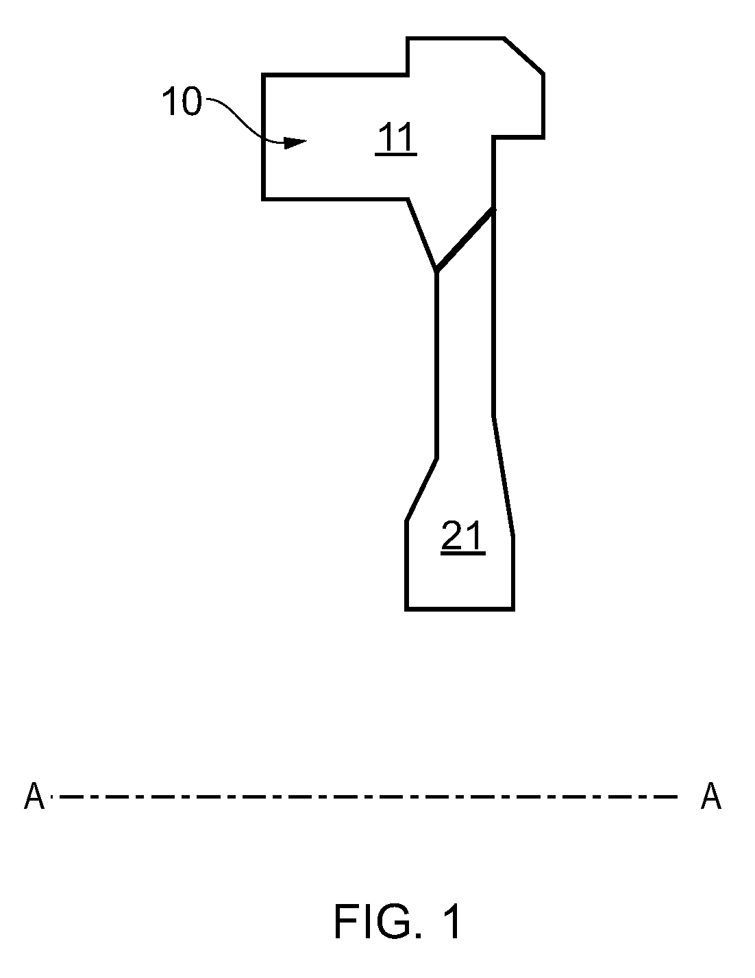
first embodiment
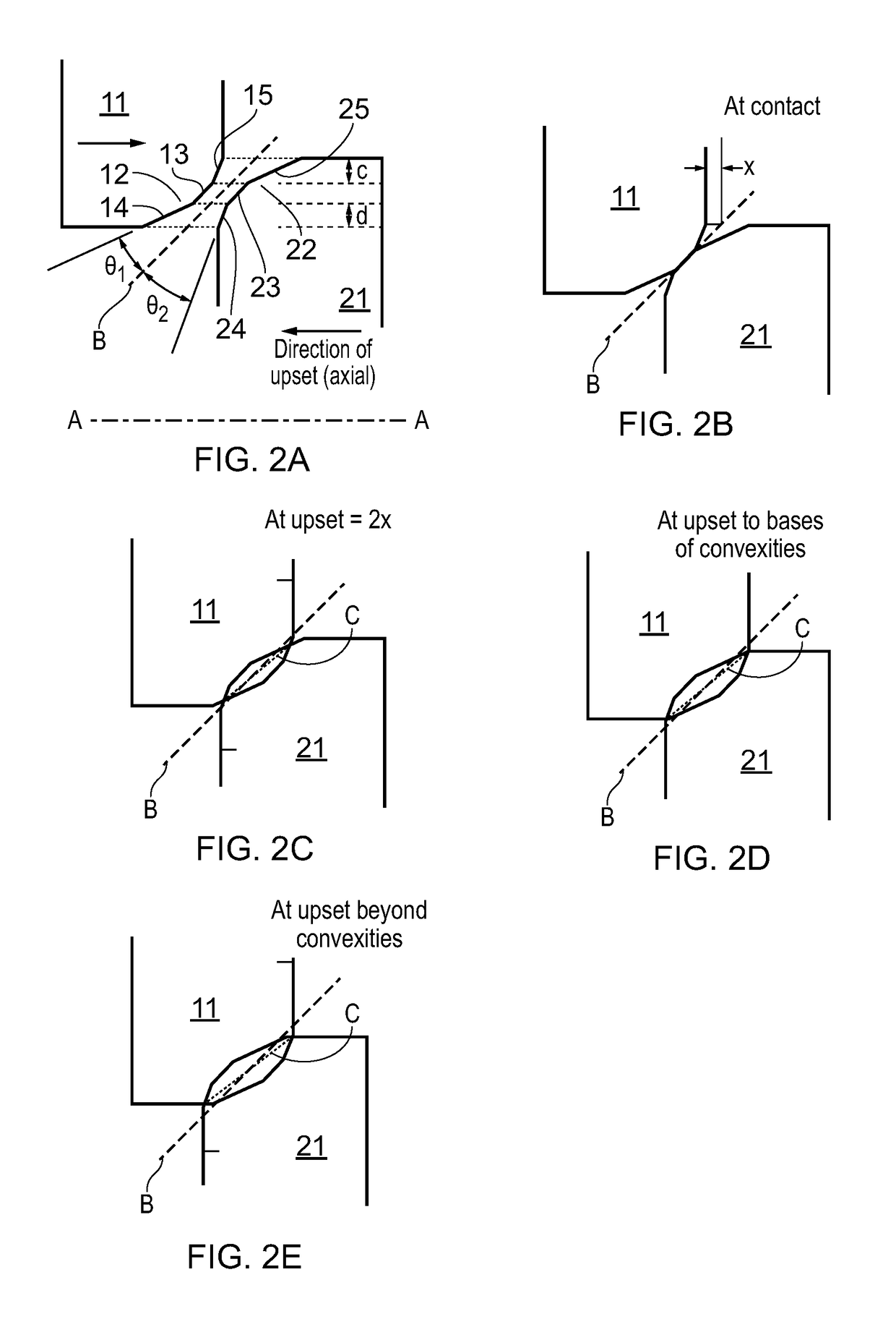
[0060]FIG. 2 shows schematically longitudinal cross-sections through a close-up at the weld surfaces of the workpieces 11, 21 of FIG. 1 to illustrate stages (a)-(e) in the rotary friction welding process used to form the disc 10.
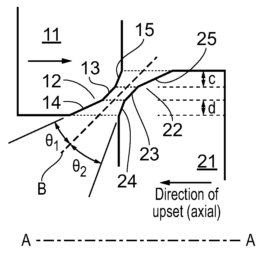
[0061]As shown in FIG. 2(a) the first workpiece 11 has a first convexity 12 at a radially inward extent of the workpiece. The apex region of the convexity 12 forms a first annular weld surface 13, with radially inner 14 and outer 15 side surfaces of the convexity 12 tapering towards the apex region. The side surface 14 is angled by an angle θ1 from the first weld surface 13 and the side surface 15 is angled by an angle θ2 from the first weld surface 13.
[0062]Similarly, the second workpiece 21 has a second convexity 22 at a radially outward extent of the workpiece. The apex region of the convexity 22 forms a second annular weld surface23, with radially inner 24 and outer 25 side surfaces of the convexity 22 tapering towards the apex region. The side surface 2...
second embodiment
[0069]FIG. 3 shows schematically longitudinal cross-sections through a close-up at the weld surfaces of the workpieces 11, 21 of FIG. 1 to illustrate stages (a)-(d) in the rotary friction welding process. Features in FIG. 3 corresponding to those in FIG. 2 have the same reference numbers.
[0070]The process is similar to that of the first embodiment except that the convexities 12, 22 are now in the form of projections from the workpieces 11, 21. This change in form of the convexities is brought about by substantially increasing the angle θ1 by which side surface 15 is angled from the first weld surface 13, and the corresponding angle θ1 by which side surface 24 is angled from the second weld surface 23. Angles θ2 for the other side surfaces 14, 25 are unchanged. On the longitudinal cross-section of FIG. 3(a), the convexities 12, 22 are still related to each other by a 2-fold axis of rotational symmetry located on the trace of surface B.
[0071]The asymmetric angles θ1, θ2 produce an asy...
third embodiment
[0073]In the third embodiment, the workpieces 11, 21 are adjusted so that the internal workpiece angles θ3, θ4, θ5, θ6 between the side surfaces 14, 15, 24, 25 and the workpiece surfaces neighbouring the projections are all the same, i.e. θ3=θ4=θ5=θ6. In contrast, in FIG. 3(a), the corresponding angles to θ3 and θ5 are significantly less than the corresponding angles to θ4 and θ6. The adjustment can be achieved by providing additional workpiece surfaces 16, 26 adjacent to side surfaces 15, 25. On the longitudinal cross-section of FIG. 4(a), the convexities 12, 22 are still related to each other by a 2-fold axis of rotational symmetry located on the trace of surface B.
[0074]The adjustment that produces θ3=θ4=θ5=θ6 helps to promote an equal heat flow at all sides of the weld interface as the upset reaches the base of the projections (FIG. 4(c)). In this way, flash flow and expulsion of contaminants in the latter stages of the consumption of the projections can still be balanced to bot...
PUM
| Property | Measurement | Unit |
|---|---|---|
| Angle | aaaaa | aaaaa |
| Angle | aaaaa | aaaaa |
| Angle | aaaaa | aaaaa |
Abstract
Description
Claims
Application Information