Method for manufacturing thermal transfer image-receiving sheet support and method for manufacturing thermal transfer image-receiving sheet

a technology of thermal transfer and image, which is applied in the direction of thermal imaging, synthetic resin layered products, printing, etc., can solve the problems of affecting the nipping of the support and the resin, the disadvantage of increasing the resin thickness, and the disadvantage of calendaring, so as to achieve high surface roughness, high rubber hardness, and high surface roughness

Active Publication Date: 2018-02-15
DAI NIPPON PRINTING CO LTD
View PDF4 Cites 1 Cited by
  • Summary
  • Abstract
  • Description
  • Claims
  • Application Information

AI Technical Summary

Benefits of technology

[0021]For the thermal transfer image-receiving sheet support and the thermal transfer image-receiving sheet manufactured by the methods according to the present invention, the cooling roller A (12) has high surface roughness, and the rubber roller A (13) has high rubber hardness. This allows the first resin layer formed on one side of the substrate to have high surface roughness. Thus, the thermal transfer image-receiving sheet support and the thermal transfer image-receiving sheet have good handleability (i.e., the property of thermal transfer image-receiving sheet supports or thermal transfer image-receiving sheets being easily handled when stacked on top of each other since they tend not to adhere to each other).
[0022]According to the present invention, the cooling roller B (22), which is used to laminate the porous film on the other side of the substrate, has low surface roughness. This allows the laminated porous film to have a smooth surface and also improves the smoothness of the colorant-receiving layer formed on the porous film through an intermediate layer, which results in good gloss. In addition, the rubber roller B (23) has low rubber hardness. This prevents (or reduces; the same applies hereinafter) the entry of air bubbles into the second resin layer and also prevents the formation of creases and other appearance irregularities.
[0023]If the surface of the substrate is corona-treated before the formation of the first resin layer on one side of the substrate or the formation of the second resin layer on the other side of the substrate, the affinity between the substrate and the resin is improved. This increases the adhesion strength of the resin to the substrate and also facilitates uniform casting of the molten resin onto the surface of the substrate, thus improving the uniformity of the resin layer.

Problems solved by technology

However, the nipping of the support and the resin is affected by the surface profile of the support.
Increasing the resin thickness is disadvantageous from a cost standpoint.
Calendaring is disadvantageous from a cost standpoint because more equipment and steps are required.
Furthermore, none of these conventional methods provides sufficient smoothness.
Thermal transfer image-receiving sheet supports manufactured by such conventional methods are unsatisfactory in terms of handleability, the prevention of air entrainment into the adhesive layer, and the gloss and condition uniformity of the resulting thermal transfer image-receiving sheets.

Method used


Image

  • Method for manufacturing thermal transfer image-receiving sheet support and method for manufacturing thermal transfer image-receiving sheet
  • Method for manufacturing thermal transfer image-receiving sheet support and method for manufacturing thermal transfer image-receiving sheet
  • Method for manufacturing thermal transfer image-receiving sheet support and method for manufacturing thermal transfer image-receiving sheet

Examples


first embodiment

[0034]First Step

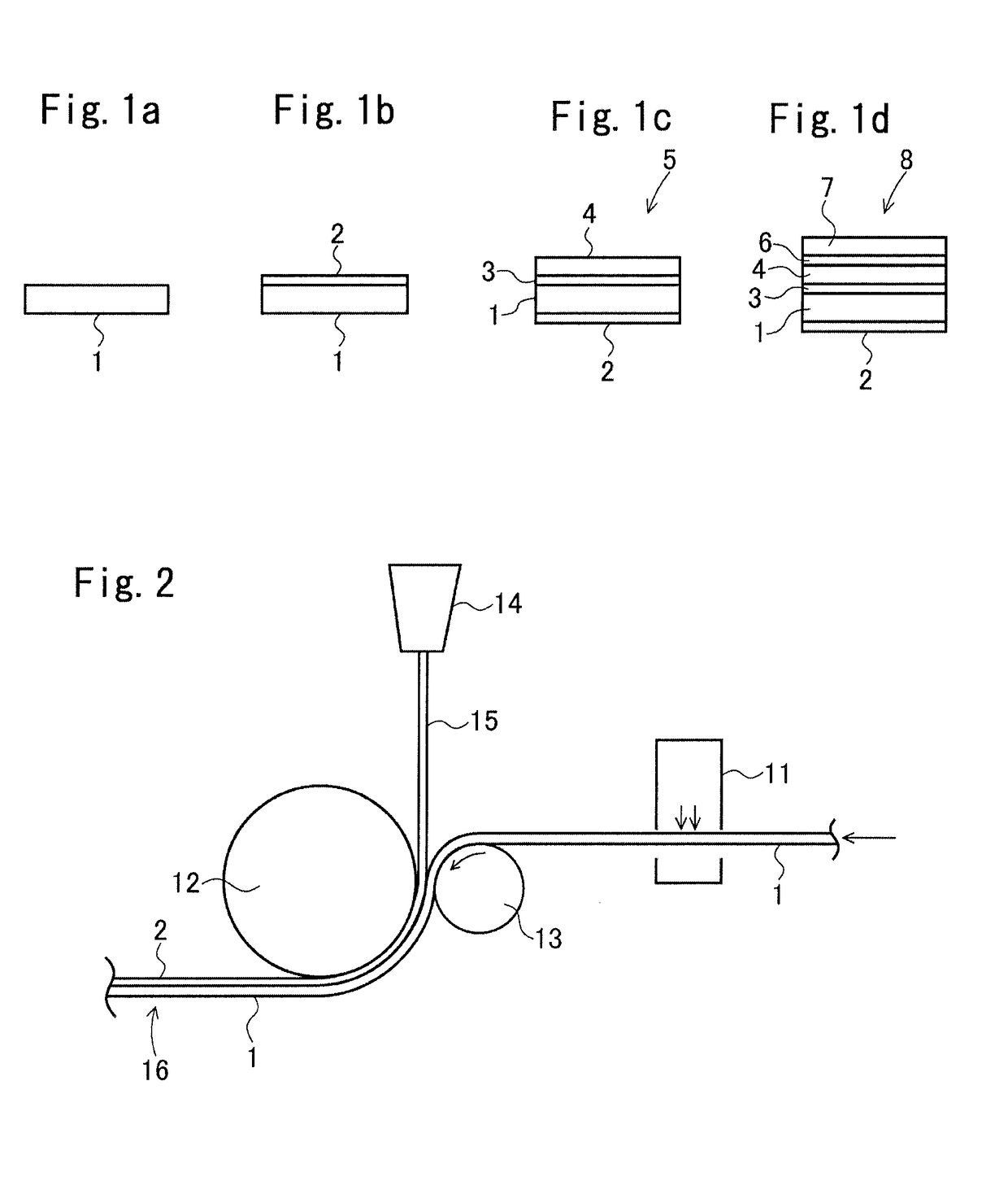
[0035]As shown in FIG. 2, in the first step of the first embodiment, while the substrate 1 is continuously fed by a feed mechanism (not shown), one side of the substrate 1 is corona-treated with a corona discharge treatment device 11, and the substrate 1 is then fed between a cooling roller (chill roller) A (12) and a rubber roller (press roller) A (13), with the one side facing the cooling roller A (12). A curtain of a first resin 15 melt-extruded from a die 14 is also supplied to the narrowest point between the cooling roller A (12) and the rubber roller A (13) or slightly closer to the rubber roller A (13) or the cooling roller A (12). The substrate 1 and the first resin 15 are stacked together and are passed between the cooling roller A (12) and the rubber roller A (13) while being held therebetween. Thus, a first laminate 16 composed of the substrate 1 and the first resin layer 2 formed by casting the resin 15 is obtained.

[0036]In this step, if the first resin 1...

second embodiment

[0043]First Step

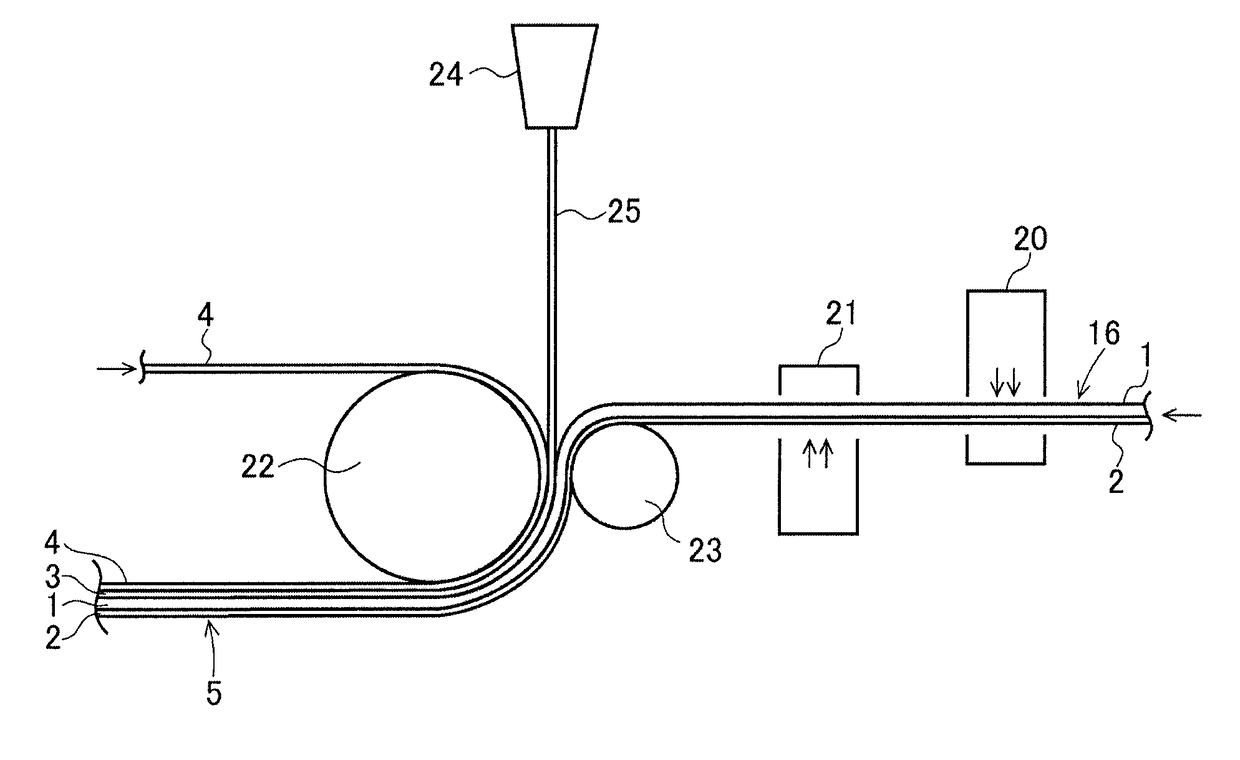
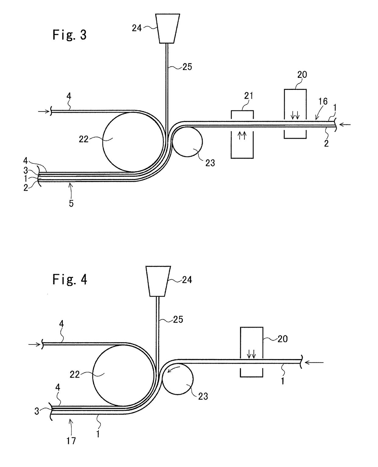
[0044]In the first step of the second embodiment, as shown in FIG. 4, while the substrate 1 is continuously fed by a feed mechanism, one side of the substrate 1 is corona-treated with a corona discharge treatment device 20, and the substrate 1 is then fed between a cooling roller (chill roller) B (22) and a rubber roller (press roller) B (23), with the one side facing the cooling roller B (22). A porous film 4 fed by a feed mechanism is also supplied between the cooling roller B (22) and the rubber roller B (23). A curtain of a second resin 25 melt-extruded from a die 24 is further supplied between the porous film 4 and the substrate 1. The porous film 4, the second resin 25, and the substrate 1 are stacked together and are passed between the cooling roller B (22) and the rubber roller B (23) while being held therebetween. Thus, a second laminate 17 composed of the substrate 1, the second resin layer 3 formed by casting the second resin 25, and the porous film 4 is o...

example 1

[0125]Manufacture of Thermal Transfer Image-Receiving Sheet Support

[0126]A paper substrate, namely, white base paper (uncoated paper with a thickness of 150 μm, available from Mitsubishi Paper Mills Limited), was provided as a substrate layer. A porous polypropylene film (with a thickness of 38 μm and a density of 0.7 g / cm3) was provided as a porous film for forming a porous film layer.

[0127]A polyethylene resin (with a melting point of 120° C. as measured in accordance with JIS K 7121 and a density of 0.95 g / cm3 as measured in accordance with JIS K 6760) was used as the first resin 15. A polyethylene resin (with a melting point of 107° C. as measured in accordance with JIS K 7121 and a density of 0.919 g / cm3 as measured in accordance with JIS K 6760) was used as the second resin.

[0128]The resin temperature during die extrusion was 320° C. for both the first resin and the second resin.

[0129]A roller having a diameter of 600 mm and having a surface with a ten-point average roughness ...


PUM

PropertyMeasurementUnit
average roughnessaaaaaaaaaa
thicknessaaaaaaaaaa
thicknessaaaaaaaaaa

Abstract

A method for manufacturing a thermal transfer image-receiving sheet support that can be used to obtain a thermal transfer image-receiving sheet that maintains its gloss and that has excellent handleability and high condition uniformity while preventing the formation of air bubbles in an adhesive layer. A resin is supplied to one side of a substrate, which is passed between a cooling roller A and a rubber roller A. A porous film is stacked on another side of the substrate through a resin, and the substrate is passed between a cooling roller B and a rubber roller B. The cooling rollers A and B have surfaces with a ten-point average roughness (Rz) of 5 to 30 μm and 0 to 20 μm, respectively. The rubber rollers A and B have a rubber hardness (durometer (Type A)) of 60 to 95 and 50 to 80, respectively.

Description

TECHNICAL FIELD[0001]The present invention relates to methods for manufacturing thermal transfer image-receiving sheet supports, and more specifically to a method for manufacturing a thermal transfer image-receiving sheet support by laminating a porous film on a substrate with a melt-extruded resin while passing the substrate and the porous film between a pair of rollers. The invention also relates to a method for manufacturing a thermal transfer image-receiving sheet by forming a colorant-receiving layer on the porous film layer of the thermal transfer image-receiving sheet support.BACKGROUND ART[0002]Recording medium supports manufactured by melt extrusion coating of at least one side of a support such as base paper with a thermoplastic resin are used after the application of other materials such as photographic emulsions and heat-sensitive materials. An important factor for achieving high-quality images on recording medium supports is the surface smoothness of the supports before...

Claims


Application Information

Patent Timeline
Patent Type & Authority Applications(United States)
IPC IPC(8): B29C43/30B29C43/52B41M5/50B32B5/18B32B27/08B32B27/06B29C43/24B29C43/46
CPCB29C43/305B29C43/24B29C43/52B29C43/46B32B5/18B32B27/08B32B27/065B41M5/502B29C2043/462B29K2883/00B29K2995/007B41M5/41B41M5/42B41M5/44B41M5/5254B41M5/5263B41M5/529B41M2205/02B41M2205/32B41M2205/36B41M2205/38
Inventor AOYAGI, MAKOTOHIRANO, KATSUYUKITAKAHASHI, TORUIESHIGE, MUNENORI
Owner DAI NIPPON PRINTING CO LTD
Why Eureka
Try Eureka