High average power optical fiber cladding mode stripper, methods of making and uses
Active Publication Date: 2018-02-15
FORO ENERGY
View PDF0 Cites 9 Cited by
Summary
Abstract
Description
Claims
Application Information
AI Technical Summary
This helps you quickly interpret patents by identifying the three key elements:
Problems solved by technology
Method used
Benefits of technology
[0019]In embodiments, the use of the present mode strippers can provide improvement in NA of the fiber at the distal or launch end of the fiber, by controlling the cladding loss. Generally, in embodiments of the present mode strippers, the mix of NA from core and cladding light is reduced or eliminated to allow only the NA from the core light propagation. Thus, for example, embodiments of the present mode strippers provide a reduction from 0.23 or 0.24 NA to values of 0.19 NA or less for a 0.22 NA fiber of >150 m length.
[0020]Additionally, there is provided, these mode strippers, methods and systems having one or more of the following features: wherein the indices of refraction are matched to within about 5% of each other; wherein the indices of refraction are matched to within about 2% of each other; where
Problems solved by technology
In transmitting high power laser energy and in performing high power laser operations, such as monitoring, welding, cladding, annealing, heating, cleaning, cutting, etching, and drilling, and in both operations and activities, the creation and propagation of undesirable laser energy can occur.
This undesirable laser energy, and in many cases and in particular as laser powers increase, has the potential to become detrimental, damaging, and potentially dangerous.
This undesirable laser energy typically is in the form of cladding transmissions, either forward or backward transmissions, from elements, such as, splices, optics, bends (macro and micro in the fiber), temperature, connectors, and work or target surfaces.
This undesirable laser energy can enter into one or more of the optical fiber's cladding layers.
Once in the cladding this undesirable laser energy can become contained, tra
Method used
Image
Click on the blue label to locate the original text in one second.
Reading with bidirectional positioning of images and text.
Examples
Embodiment Construction
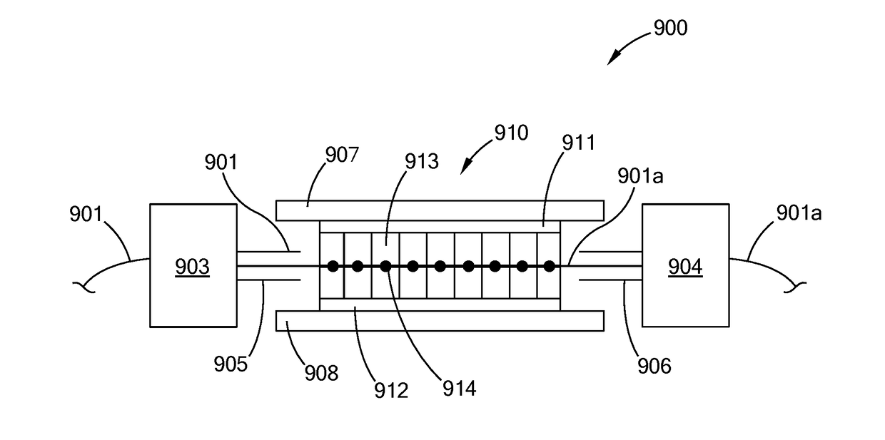
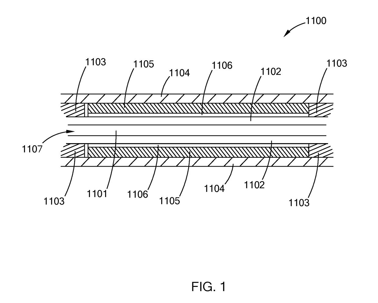
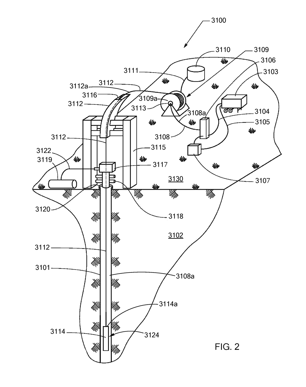
[0060]In general, the present inventions relate to systems, methods and tools for transmitting and applying high laser beams and high power laser energy to perform laser operations, such as monitoring, welding, cladding, annealing, heating, cleaning, spelling, melting, ablating, vaporizing, drilling, cutting, and etching. In particular, the present inventions relate to methods and devices to remove undesirable laser energy from a laser system and generally from fiber optics in such a system. The present inventions further relate to mode strippers located on, or as a part of, optical fibers and which remove undesirable laser energy from the cladding of the optical fiber. Preferably, embodiments of the present mode strippers remove these undesirable laser energies, from the cladding of the optical fiber, while preferably not disrupting the transmission of the operable laser energy (e.g., the laser beam being transmitted in the core of the fiber and intended to perform a laser operatio...
PUM
Abstract
Nano-particle based mode strippers for removing undesirable laser energy for laser systems. Nano-particle mode strippers having matched indices of refraction to the outer cladding remove cladding light converting it into heat. There are provided fibers having evanescent mode strippers having annular outer cores and claddings.
Description
[0001]This application:[0002](i) claims under 35 U.S.C. § 119(e)(1), the benefit of filing of provisional patent application Ser. No. 62 / 410,724 filed Oct. 20, 2016; and,[0003](ii) is a continuation-in-part of U.S. patent application Ser. No. 15 / 147,269, filed May 5, 2016, which is a divisional of U.S. patent application Ser. No. 13 / 486,795 filed Jun. 1, 2012, now U.S. Pat. No. 9,360,643, and which claims under 35 U.S.C. § 119(e)(1), the benefit of filing of provisional patent application Ser. No. 61 / 605,413 filed Mar. 1, 2012 and Ser. No. 61 / 493,174 filed Jun. 3, 2011;[0004]the entire disclosures of each of which are incorporated herein by reference.BACKGROUND OF THE INVENTIONField of the Invention[0005]The present inventions relate to high power laser systems, high power laser fibers for the delivery of high power laser energy to nearby, as well as, remote and difficult to access locations, high power laser tools, and other high power laser systems and applications, and in particu...
Claims
Application Information
Patent Timeline
Application Date:The date an application was filed.
Publication Date:The date a patent or application was officially published.
First Publication Date:The earliest publication date of a patent with the same application number.
Issue Date:Publication date of the patent grant document.
PCT Entry Date:The Entry date of PCT National Phase.
Estimated Expiry Date:The statutory expiry date of a patent right according to the Patent Law, and it is the longest term of protection that the patent right can achieve without the termination of the patent right due to other reasons(Term extension factor has been taken into account ).
Invalid Date:Actual expiry date is based on effective date or publication date of legal transaction data of invalid patent.