Dual-beam laser beam recorder, and method for controlling a dual-beam laser recorder

Inactive Publication Date: 2009-03-12
MOSER BAER INDIA
View PDF5 Cites 1 Cited by
  • Summary
  • Abstract
  • Description
  • Claims
  • Application Information

AI Technical Summary

Benefits of technology

[0018]In accordance with a further embodiment of the present invention it is possible that at least some of the pits have different depths. By providing pits having different depths it is possible to create ROM media with basically more than two transmission / reflection levels to increase the data density.
[0025]In accordance with a different field of application the stamper is intended to be used for printing, especially for micro-contact printing. If the patterned substrate serves as stamp(er), an additional thin coating can be applied to improve or reduce the wetting properties of the information side of the stamp(er).
[0026]To further increase the data density it is possible that the track is a meta-track comprising a two dimensional data layout. The two-dimensional data storage in the disc plane is a novel way to increase capacity. The anticipated data capacity of a two-dimensional data storage is estimated to be at least at a factor 2.
[0028]It is highly preferred that at least one of the two laser beams is deflected to enhance the spatial resolution. In general, a deflector increases the span of the focused laser spot during one passage of the spot. The deflection of the beam is very fast (up to 40 MHz in combination with 200 nm amplitude deflection is possible, the speed of deflection can be increased on the cost of the deflection amplitude). To write the data, at a fixed reference point in time, the rotation of the disc is synchronized with the laser pulse pattern. If the disc rotates at a constant angular velocity, the time of one revolution is fixed, namely T=1 / f, f being the rotational frequency of the disc (angular frequency ω=2πf). The 
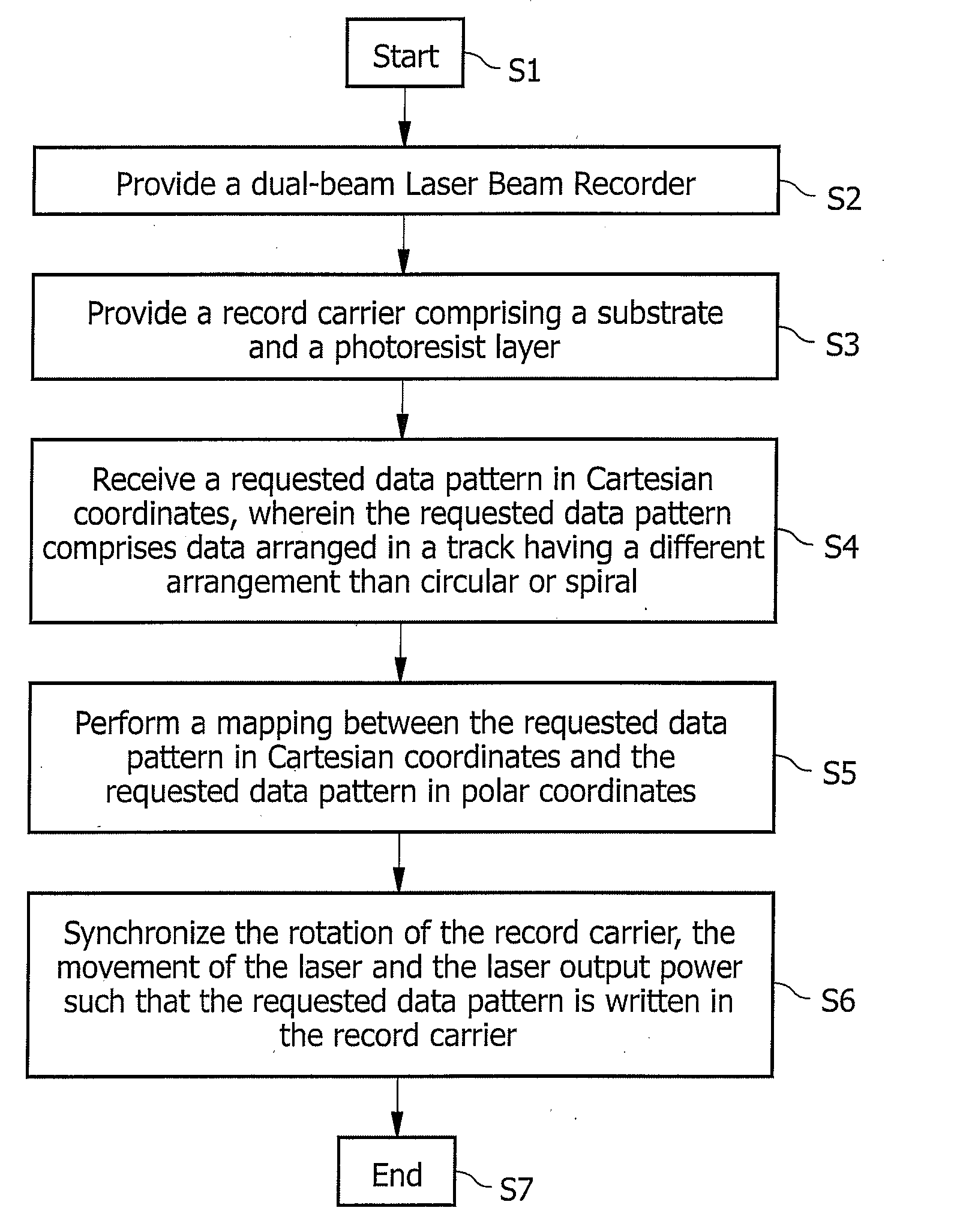
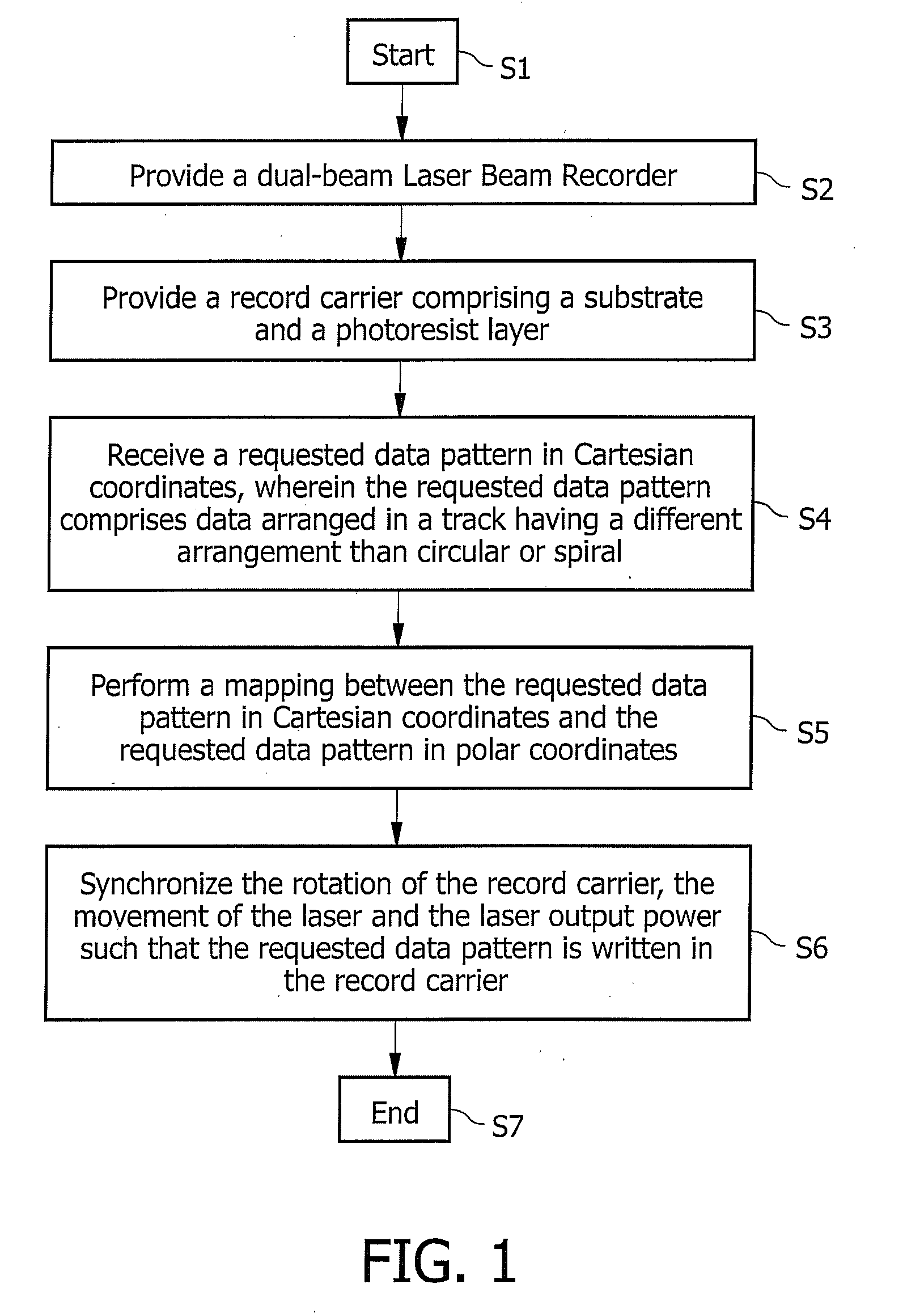
delay between the reference point and Pit P(i,j) is t=θ / ω. At time t, the write pulse is fired to write pixel or pit P(i,j). It is also possible to operate the LBR in constant linear velocity mode. The angular velocity is then adapted to obtain a constant linear velocity at all radii. For a known data pattern, the to be written pits are known in terms of Cartesian coordinates, as mentioned above. These locations of the pits are transformed to polar co-ordinates (angle and radius) once the origin of the pattern is fixed. Subsequently the laser pulse train can be defined and synchronized with the rotation of the disc. If a very low track pitch is selected for a single-beam LBR, for instance 10 nm, theoretically no deflection is required to achieve a position resolution of 10 nm. The spot size is 150 nm based on a deep UV LBR recorder (257 nm wavelength and an NA=0.9, with liquid immersion mastering, the NA of the spot can be further increased to NA=1.2). Features (lines) with width of 150 nm can be written. The position accuracy is about 10 nm. However, the total recording time is between 60 hours (2 m / s recording velocity) and 20 hours (5 m / s recording velocity). If a track pitch of 400 nm is selected with no deflection or second laser beam, the position accuracy is less than 200 nm and in most cases unacceptable. If the track pitch is 400 nm, a deflection of 200 nm is possible. The deflection frequency is 40 MHz, corresponding to 25 ns deflection time. In case of a linear velocity of 2 m / s, 25 ns corresponds to 50 nm displacement. The total recording time is 2 hours. In combination with a dual-beam LBR deflection of at least one laser beam makes all positions possible.

Problems solved by technology

However, E-beam patterning is expensive and time-consuming.
A major disadvantage of conventional optical storage concepts is the presence of rotating parts in the optical drives.
Rotating parts have a lot of disadvantages, for example a sensitivity to wear, a creation of noise due to rotation, a consumption of rather high electrical power, in particular at high rotation speeds, etc.
A main challenge is the manufacturing of suitable ROM media for such readers.
This dissolution results in physical holes inside the photoresist layer.

Method used


Image

  • Dual-beam laser beam recorder, and method for controlling a dual-beam laser recorder
  • Dual-beam laser beam recorder, and method for controlling a dual-beam laser recorder
  • Dual-beam laser beam recorder, and method for controlling a dual-beam laser recorder

Examples


Embodiment Construction

[0054]FIG. 1 is a flow chart illustrating an embodiment of the method in accordance with the invention. The illustrated method starts in step S1. In step S2 a dual-beam Laser Beam Recorder is provided which will be described in greater detail with reference to FIG. 2. In step S3 a record carrier comprising a substrate and a recording stack is provided. For conventional mastering, the recording stack comprises a photoresist layer. It should be clear that optionally other layers may also be provided, for example layers to improve the absorption of the laser light and to improve the pit shape. It is also possible to use a master substrate based on phase-transition materials. Furthermore, it should be clear that in cases where pits comprising different depths are to be created, record carriers comprising a corresponding number of recording layers may be used. In step S4 a requested data pattern is received in Cartesian coordinates. The requested data pattern comprises data arranged in a...


PUM


Abstract

The present invention relates to a method for controlling a dual-beam LBR (Laser Beam Recorder) (56) suitable for mastering a record carrier (60) by writing data in the record carrier in circular or spiral tracks and comprising: means (58) for rotating a record carrier; means (62) for moving a dual-beam laser (61) over the record carrier (60) in a radial direction with reference to the rotation of the record carrier (60); means (65) for controlling the dual-beam laser output power; and means (66) for synchronizing the rotation of the record carrier (60), the movement of the dual-beam laser (61) and the dual-beam laser output power.In accordance with the invention synchronizing the rotation of the record carrier 60; the movement of the dual-beam laser 61 and the dual-beam laser output power is performed such that at least a part of the data is written in at least one track comprising a different arrangement than circular or spiral.The present invention also relates to a dual-beam Laser Beam Recorder adapted to carry out the method of the invention, and to the use of such a dual-beam Laser Beam Recorder to create a high density relief structure which at least in sections comprises a different arrangement than circular or spiral.

Description

FIELD OF THE INVENTION[0001]The present invention relates to a method for controlling a dual-beam LBR (Laser Beam Recorder) suitable for mastering a record carrier by writing data in the record carrier in circular or spiral tracks and comprising: means for rotating a record carrier; means for moving a dual-beam laser over the record carrier in a radial direction with reference to the rotation of the record carrier; means for controlling the laser output power; and means for synchronizing the rotation of the record carrier, the movement of the dual-beam laser and the laser output power. Furthermore, the present invention relates to a dual-beam Laser Beam Recorder suitable for mastering a record carrier by writing data in the record carrier in circular or spiral tracks and comprising: means for rotating a record carrier; means for moving a dual-beam laser over the record carrier in a radial direction with reference to the rotation of the record carrier; means for controlling the dual-...

Claims


Application Information

Patent Timeline
IPC IPC(8): G11B7/00
CPCB82Y10/00B82Y40/00G11B7/261G11B7/0033G03F7/0002
Inventor MEINDERS, ERWIN R.
Owner MOSER BAER INDIA
Why Eureka
Try Eureka