Device, method and system for generating dynamic projection patterns in a camera

Active Publication Date: 2019-12-12
DENTSPLY SIRONA INC
View PDF5 Cites 7 Cited by
  • Summary
  • Abstract
  • Description
  • Claims
  • Application Information

AI Technical Summary

Benefits of technology

This patent describes a device, method, and system for using an optical array generator to create dynamic patterns on the surface of an object for three-dimensional (3D) measurement. The system uses projected light patterns and optical triangulation principles to measure the object's surface geometry. By using various structured illumination patterns and noise reduction techniques, the system can measure the 3D profile of objects with high accuracy. In summary, this technology allows for non-contact and accurate 3D surface profiling of objects.

Problems solved by technology

A problem arises if the object being measured is translucent.
A reduced contrast may result in the inability to detect the projected features since the noise may become greater than the signal amplitude.
However, this is technically limited by the full-well capacities of the image sensor pixels.
Furthermore, the “object noise” (disturbances caused by the object itself e.g. from a rough surface or a non-uniform coloring) cannot be reduced by increasing the amount of light.
However, if the surface of the object is non-planar, the projected structured-light pattern in the corresponding image may be distorted by the surface geometry.

Method used


Image

  • Device, method and system for generating dynamic projection patterns in a camera
  • Device, method and system for generating dynamic projection patterns in a camera
  • Device, method and system for generating dynamic projection patterns in a camera

Examples


Embodiment Construction

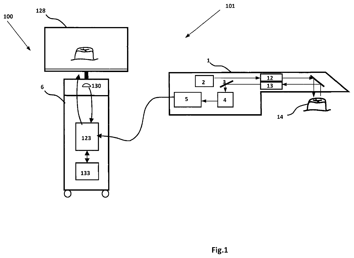
[0023]In accordance with example aspects described herein, a device, method and system are provided for generating dynamic patterns in a camera for example a dental camera for projection onto the surface of an object for three-dimensional (3D) measurement.

[0024]In one aspect, an optical array generator 2 for generating projection patterns may be provided in a camera 1, for example a dental camera. The optical array generator may comprise a collimator 21, an LED array 20 and a lens array 22. The collimator 21 may be constructed to direct light of the LED array 20 onto the lens array 22 which comprises sub lenses 25. A computer system 100 may control and synchronize (i) exposure times of image sensors 4 and (ii) the LEDs of the LED array 20 to emit light in a predetermined pattern. For example, some LEDs may be turned on at the same time as other LEDs are turned off to produce a predetermined pattern of structured light. In an embodiment herein, a temporal lighting sequence of the LED...


PUM


Abstract

A device, method and system for utilizing an optical array generator to generate dynamic patterns in a dental camera for projection onto the surface of an object, while reducing noise and increasing data density for three-dimensional (3D) measurement. Projected light patterns are used to generate optical features on the surface of the object to be measured and optical 3D measuring methods which operate according to triangulation principles are used to measure the object.

Description

BACKGROUNDField[0001]The present application relates generally to a device for generating dynamic projection patterns in a camera, and, more particularly, to a device, method and system for utilizing an optical array generator to generate dynamic patterns in a camera for projection onto the surface of an object for three-dimensional (3D) measurement.Description of Related Art[0002]In structured light scanning methods such as fringe projection, objects may be illuminated with structured patterns of light such as sinusoidal fringe patterns. The structured patterns may be geometrically distorted or phase modulated by the objects and then recorded as images with a camera at a known angle with respect to the projections. Techniques such as Fourier transforms may be used to calculate the distortions, displacements or phase modulations by analyzing the recorded images. For example, using a suitable phase unwrapping algorithm, pattern recognition or edge detection method, depth cues in reco...

Claims


Application Information

Patent Timeline
IPC IPC(8): H04N13/254G06T7/521G02B3/00G02B19/00G02B5/20
CPCH04N13/254G02B19/0066G02B27/30G02B5/201G06T2207/10012G02B19/0014G02B3/0056G06T7/521A61C9/006G01B11/25G01B11/2513G02B3/005G02B3/0068H04N23/55
Inventor TEWES, MICHAEL
Owner DENTSPLY SIRONA INC
Why Eureka
Try Eureka