Computerized device and method for processing image data

a computerized device and image data technology, applied in the field of image data processing, can solve the problems of severe vision loss, the method described in reference [1] has disadvantages in the calculation speed and the necessary accuracy, and achieve the effect of enhancing the accuracy of the processing uni

Active Publication Date: 2018-02-15
RETINSIGHT GMBH
View PDF11 Cites 20 Cited by
  • Summary
  • Abstract
  • Description
  • Claims
  • Application Information

AI Technical Summary

Benefits of technology

[0031]In particular, besides the visional appearance of the image patches, the convolutional neural network may be provided with the Euclidean distances of the patch centers to the fovea and the three-dimensional coordinates of the patch centers. Therefore, the accuracy of the processing unit is further enhanced advantageously. Moreover, based on the image patches of the training set, the convolutional neural network may learn representative and discriminative features appropriate for pixel-wise image classification of the optical coherence tomography data. The pixel-wise classification may result in a segmentation of the whole optical coherence tomography volume into normal retinal tissue, intraretinal cystoid fluid and subretinal fluid.

Problems solved by technology

Out of the two components of retinal edema, intraretinal cystoid fluid (IRC) leads to severe vision loss.
But, the method described in reference [1] has disadvantages in the calculating speed and in the necessary accuracy.

Method used


Image

  • Computerized device and method for processing image data
  • Computerized device and method for processing image data
  • Computerized device and method for processing image data

Examples


first embodiment

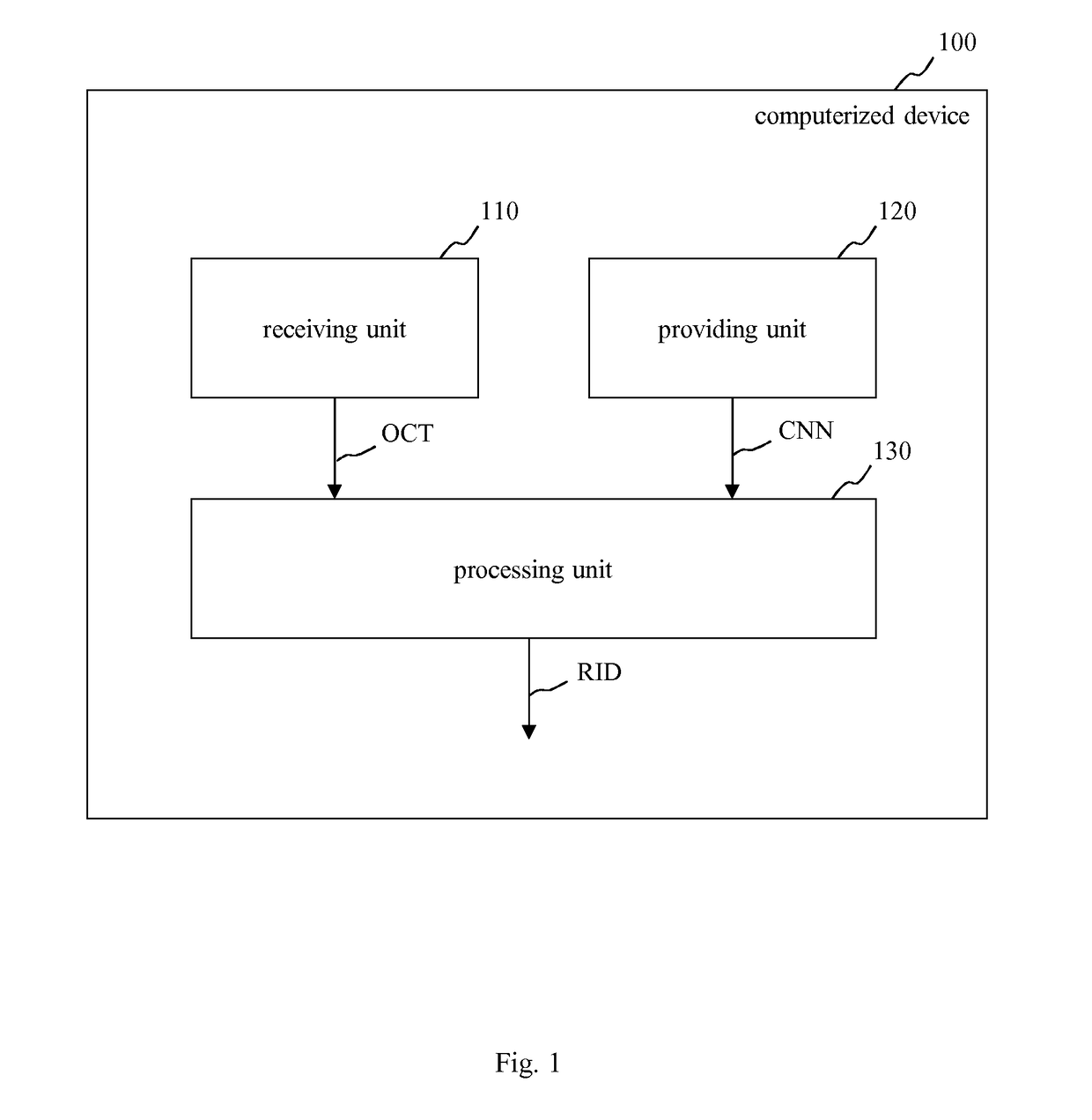
[0063]In FIG. 4, a schematic view of a convolutional neural network CNN that may be used by the computerized device 100 of FIG. 1 is depicted.

[0064]The convolutional neural network CNN of FIG. 4 may be trained by a plurality of two-dimensional image patches TP1 extracted from a number of spectral-domain optical coherence tomography images OCT. As shown on the left side of FIG. 4, the respective two-dimensional image patch TP1 is extracted from said spectral-domain optical coherence tomography image OCT and input into a layer stack S1 of the convolutional neural network CNN. The layer stack S1 of FIG. 4 has three pairs P11, P12 and P13 of convolutional layers CONV1-CONV3 and respectively succeeding max-pooling layers MP1-MP3.

[0065]As shown in FIG. 4, the two-dimensional image patch TP1 has a size of 35×35. Further, as shown in FIG. 4, the resulting outputs OUTk of the k pairs of convolutional layer CONVk and max-pooling layer MPk are the inputs of the succeeding layers (with kε[1, 2,...

second embodiment

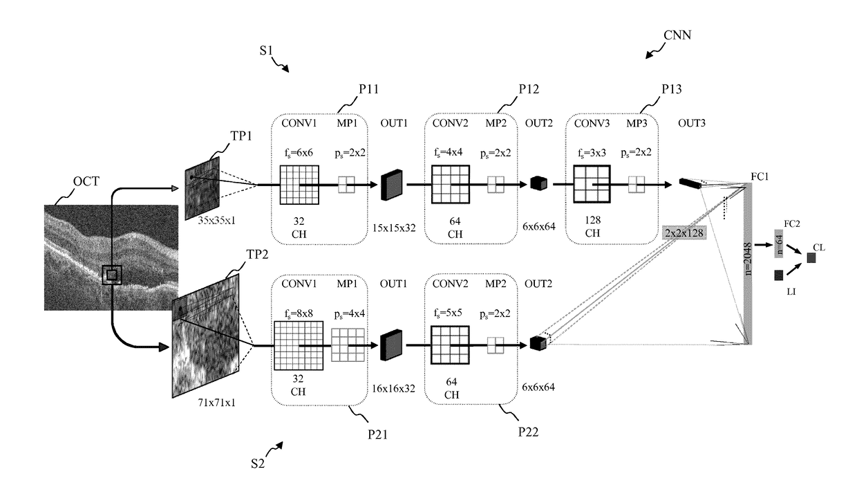
[0068]FIG. 5 shows a schematic view of a convolutional neural network CNN which may be used by the computerized device 100 of FIG. 1.

[0069]In contrast to the embodiment of FIG. 4, the convolutional neural network CNN of FIG. 5 includes two different layer stacks S1 and S2. The layer stack S1 uses first two-dimensional image patches TP1 extracted from the optical coherence tomography data OCT. For example, said first two-dimensional image patches TP1 have a size of 35×35, respectively.

[0070]The second layer stack S2 uses second two-dimensional image patches TP2 having a size of 71×71. In particular, the different two-dimensional image patches TP1 and TP2 have different sizes, here 35×35 and 71×71, but are centered at the same position, respectively.

[0071]As shown in FIG. 5, the outputs of both layer stacks S1, S2 are connected densely with all neurons of the first fully-connected layer FC1. As in FIG. 4, the location information LI are fed jointly with the activations of the second f...


PUM


Abstract

A computerized device (100) for processing image data (OCT, RID) is proposed. The computerized device (100) comprises a receiving unit (110) which is configured to receive optical coherence tomography data (OCT) of a of a tissue, in particular of a retina, a providing unit (120) which is configured to provide a convolutional neural network (CNN) for processing the optical coherence tomography data (OCT), and a processing unit (130) which is configured to process the received optical coherence tomography data (OCT) using the convolutional neural network (CNN) for identifying at least one certain object (IRC, SRF) in the tissue.

Description

FIELD OF THE INVENTION[0001]The present invention relates to a computerized device and to a method for processing image data. The technical field of the present invention is the processing of image data, like medical image data. For example, said medical image data may be optical coherence tomography data provided by an optical coherence tomography scanner (OCT scanner).BACKGROUND[0002]In particular, a key driver for vision loss in retinal diseases such as neovascular age-related macular degeneration is the accumulation of retinal edema or fluid. Out of the two components of retinal edema, intraretinal cystoid fluid (IRC) leads to severe vision loss. Conversely, recent evidence suggests that subretinal fluid (SRF) may be associated with better visual acuity. A precise classification and quantification of IRC and SRF may be of great importance for disease management. Similarly, a wide spectrum of other quantifiable morphologic objects may be present in the retina, which may be releva...

Claims


Application Information

Patent Timeline
Patent Type & Authority Applications(United States)
IPC IPC(8): G06T7/00G06N3/08A61B3/10G06F17/15G06N3/04G06V10/764
CPCG06T7/0012G06F17/15G06N3/04A61B3/102G06N3/08G06T2207/30041G06T2207/10101G06T2207/20084G06V10/764G06F18/24
Inventor SCHLEGL, THOMASVOGL, WOLF-DIETERLANGS, GEORGWALDSTEIN, SEBASTIANGERENDAS, BIANCASCHMIDT-ERFURTH, URSULA
Owner RETINSIGHT GMBH
Why Eureka
Try Eureka