Blood pump

a technology of blood pump and impeller, which is applied in the field of blood pump, can solve the problems of increased mechanical wear, increased heat, and subject to mechanical wear, and achieve the effects of reducing the vibration of the impeller during critical speeds, high advantageous to heart recovery, and small siz

Active Publication Date: 2018-02-22
ABIOMED EURO
View PDF3 Cites 36 Cited by
  • Summary
  • Abstract
  • Description
  • Claims
  • Application Information

AI Technical Summary

Benefits of technology

[0016]It will be appreciated that according to the invention two mechanical bearing are employed to center the impeller. The spatial distribution of both bearings along the axis of rotation allows for a stiff bearing / impeller arrangement. The later allows for pulsatile pump operation where the impeller may transfer from below critical speeds with every heart cycle. Due to the stiff arrangement provided by the two mechanical bearings, vibration of the impeller during critical speeds can be reduced. The pulsatile and synchronized pump operation with the heart is considered to be highly advantageous to achieve heart recovery. In addition it will be appreciated that mechanical bearings are employed because of their small size, which is mandated by any small sized pump intended to be placed inside a patient's vessel.

Problems solved by technology

Contact-type bearings, such as pivot bearings, may heat up during use and are subject to mechanical wear.
Mechanical wear may be increased by a magnetic coupling between the electric motor of the pump and the impeller for driving the impeller.
When the contact-type bearing and the magnetic coupling are disposed at the same axial end of the impeller, mechanical wear of the bearing may increase because the magnetic coupling attracts the impeller, thereby increasing the contact pressure on the bearing surfaces.

Method used


Image

  • Blood pump
  • Blood pump
  • Blood pump

Examples


Embodiment Construction

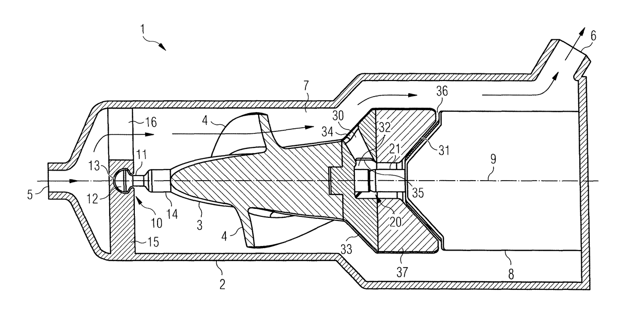
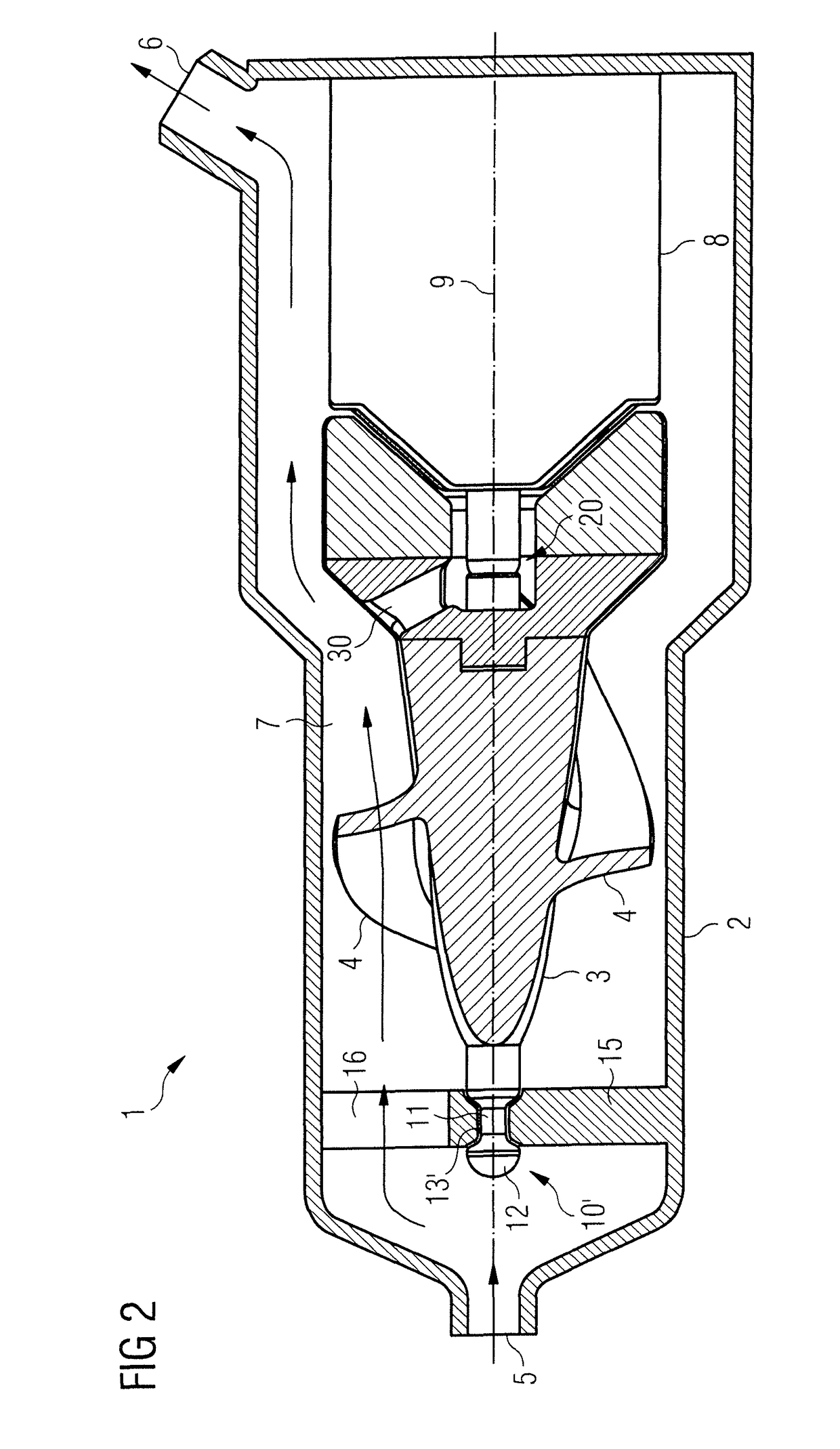
[0033]Referring to FIG. 1, a cross sectional view of a blood pump 1 is illustrated. The blood pump 1 is designed for extracorporeal, extracardiac or extraluminal use and comprises a pump casing 2 with a blood flow inlet 5 and a blood flow outlet 6. During operation, the pump casing 2 is placed outside a patient's body and the blood flow inlet 5 and the blood flow outlet 6 are connected to respective connectors (in particular inflow from the heart and outflow to the aorta). The blood is conveyed along a passage 7 connecting the blood flow inlet 5 and the blood flow outlet 6. An impeller 3 having a shaft 14 is provided for conveying blood along the passage 7 and is rotatably mounted about an axis of rotation 9 within the pump casing 2 by means of a first bearing 10 and a second bearing 20. The axis of rotation 9 is preferably the longitudinal axis of the impeller 3. Both bearings 10, 20 are contact-type bearings as will be described in more detail below. The second bearing 20 is a piv...


PUM


Abstract

A blood pump (1) comprises a pump casing (2) having a blood flow inlet (5) and a blood flow outlet (6) connected by a passage (7), and an impeller (3) arranged in said pump casing (2) so as to be rotatable about an axis of rotation (9). The impeller (3) is provided with blades (4) sized and shaped for conveying blood along the passage (7) from the blood flow inlet (5) to the blood flow outlet (6), and is rotatably supported in the pump casing (2) by a first bearing (10) at a first axial end of the impeller (3) and a second bearing (20) axially spaced apart from the first bearing (10). The first bearing (10) comprises a projection (11) extending along the axis of rotation (9) and connected to one of the impeller (3) and the pump casing (2) and a cavity (13) in the other one of the impeller (3) and the pump casing (2), the projection (11) comprising an enlarged portion (12) that engages the cavity (13) such that the first bearing (10) and the second bearing (20) are arranged to bear axial forces in the same axial direction.

Description

BACKGROUND[0001]This invention relates to blood pumps to be implanted in a patient for supporting the patient's heart. In particular, the blood pump may be used as a “bridge to recovery” device, whereby the blood pump temporarily supports the patient's heart until it has sufficiently recovered.[0002]Blood pumps of different types are known, such as axial blood pumps, centrifugal blood pumps or mixed type blood pumps, where the blood flow is caused by both axial and radial forces. Blood pumps may be inserted into a patient's vessel such as the aorta by means of a catheter, or may be placed in the thoracic cavity. A blood pump typically comprises a pump casing having a blood flow inlet and a blood flow outlet connected by a passage. In order to cause a blood flow along the passage from the blood flow inlet to the blood flow outlet an impeller is rotatably supported within the pump casing, with the impeller being provided with blades for conveying blood.[0003]The impeller is supported ...

Claims


Application Information

Patent Timeline
Patent Type & Authority Applications(United States)
IPC IPC(8): A61M1/10A61M60/13A61M60/221A61M60/232A61M60/237A61M60/422A61M60/82A61M60/825
CPCA61M1/1013A61M2205/3334A61M60/221A61M60/825A61M60/237A61M60/232A61M60/13A61M60/422A61M60/824A61M60/165A61M60/211A61M60/419A61M60/148A61M60/818A61M60/82A61M60/135A61M60/414
Inventor SIESS, THORSTENABOUL-HOSN, WALID
Owner ABIOMED EURO
Why Eureka
Try Eureka