Microwave ignition of electrically operated propellants

a technology of electrically operated propellants and microwave energy, which is applied in the direction of rocket engine plants, machines/engines, explosions, etc., can solve the problems of substantially all the propellant, the srm propellant cannot be “turned off” and “burned back”, and achieve the effect of efficient couplement of microwave energy

Active Publication Date: 2018-02-22
RAYTHEON CO
View PDF2 Cites 8 Cited by
  • Summary
  • Abstract
  • Description
  • Claims
  • Application Information

AI Technical Summary

Benefits of technology

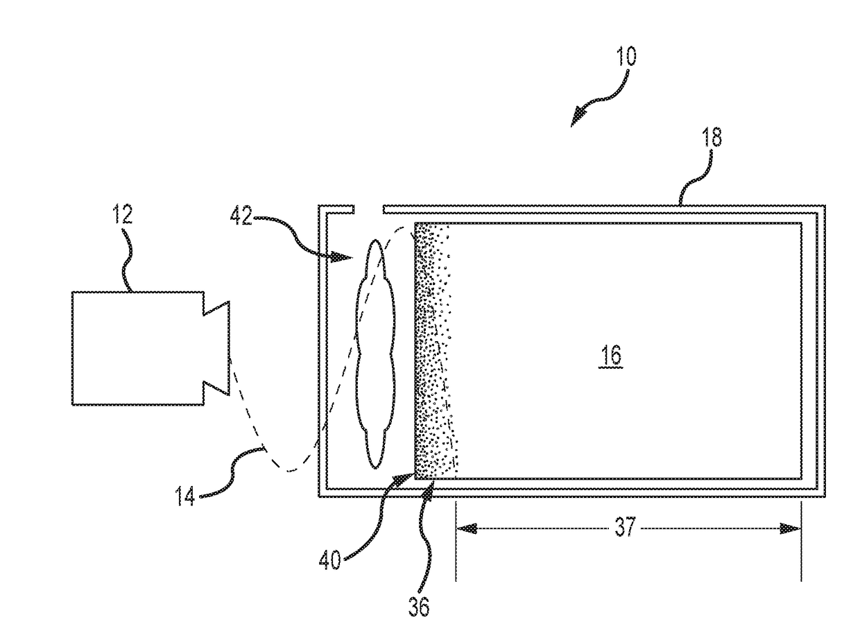
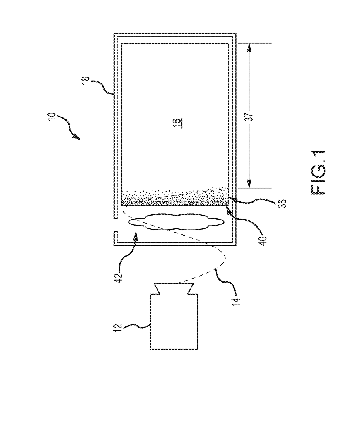
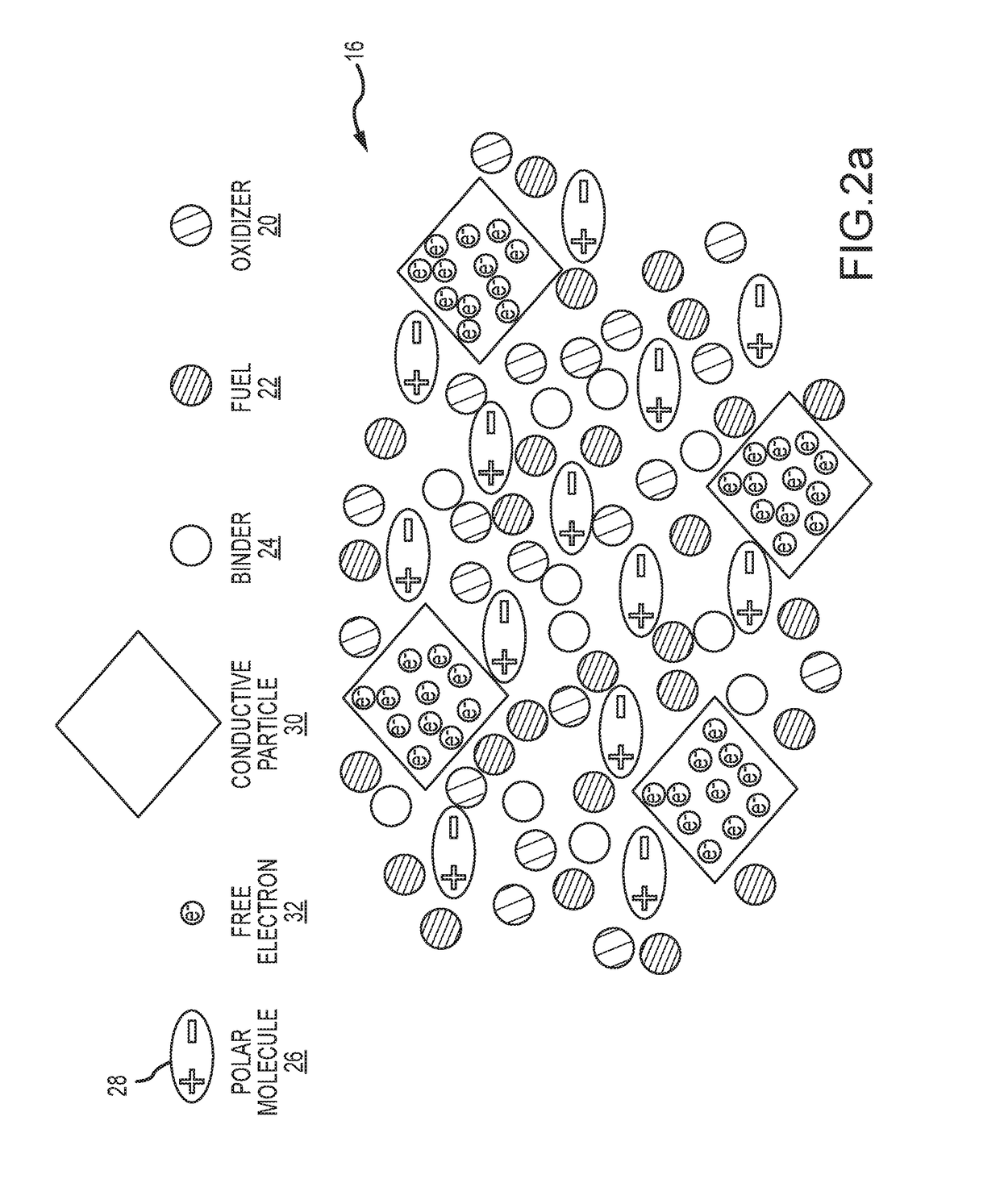
[0014]In an ignition condition, incoming microwave energy creates an electric field E within an attenuation zone of the propellant that oscillates at the microwave frequency. The electric field E causes the free electrons to accumulate at conductive particles of high potential and be discharged in the form of dielectric breakdowns through the other constituents of the propellant to conductive particles of low potential. These discharges form randomly oriented local currents that exhibit local current densities J that exceed an electrical ignition threshold. The electric field E also causes the polar molecules to vibrate rapidly, which raises the temperature of the propellant above a thermal ignition threshold in the attenuation zone. In this ignition condition, an ignition surface of the attenuation zone ignites and burns as the zone regresses without igniting the remaining bulk of the propellant to generate gaseous byproducts that pressurize a combustion chamber.
[0016]In an embodiment, to efficiently couple microwave energy to the attenuation zone, an anti-node (peak of the oscillating wave) of the microwave energy is positioned at the ignition surface. In one embodiment, the phase of the microwave energy is modulated such that the anti-node tracks the position of the ignition surface as the attenuation zone regresses. In another embodiment, an actuator displaces the propellant to hold the ignition surface in place at the fixed anti-node of the microwave energy.

Problems solved by technology

SRM propellants typically exhibit a designed burn rate and consume substantially all of the propellant.
Furthermore, once ignited, SRM propellants cannot be “turned off” except by a violent and uncontrolled depressurization.
A challenge to achieve wide spread use is to provide an electrode configuration that provides for control of the ignition surface and burn rate and efficient consumption of substantially all of the propellant, and one that is scalable to combust greater propellant mass to support larger gas generation systems.
“Burn Back” as this is referred is an uncontrolled and inefficient process to ignite and consume propellant.
In one example, the electrodes are in electrical contact with the electrically ignitable propellant and are supplied a direct current, which may cause combustion of the electrically ignitable propellant at the contact location of the positive electrode with the electrically ignitable propellant.

Method used


Image

  • Microwave ignition of electrically operated propellants
  • Microwave ignition of electrically operated propellants
  • Microwave ignition of electrically operated propellants

Examples


Embodiment Construction

[0028]The present invention provides for microwave ignition of electrically operated propellant. Microwave ignition overcomes the issue of “burn back” exhibited by various electrode configurations. Microwave ignition is scalable to combust greater propellant mass to support larger gas generation systems.

[0029]Referring now to FIGS. 1, 2a and 2b, a gas generation system 10 includes a source 12 (e.g. a magnetron) configured to generate microwave energy 14 in a defined microwave band between 0.3 GHz and 300 GHz, a mass of electrically operated propellant 16 and a combustion chamber 18. Typically, the walls of the chamber around the mass of propellant are impermeable to the microwave energy and the far wall opposite the mass is permeable to the microwave energy. The microwave band is generally a narrow band above a center frequency Fc. The band is typically at most + / −10% of Fc and more typically + / −5% of Fc. In certain embodiments, Fc lies between 1 and 10 GHz.

[0030]The electrically op...


PUM

PropertyMeasurementUnit
center frequencyaaaaaaaaaa

Abstract

Microwave energy is used to ignite and control the ignition of electrically operated propellant to produce high-pressure gas. The propellant includes conductive particles that act as a free source of electrons. Incoming microwave energy accumulates electric charge in an attenuation zone, which is discharged in the form of dielectric breakdowns to create local randomly oriented currents. The propellant also includes polar molecules. The polar molecules in the attenuation zone absorb microwave energy causing the molecules to rapidly vibrate thereby increasing the temperature of the propellant. The increase in temperature and the local current densities together establish an ignition condition to ignite and sustain ignition of an ignition surface of the attenuation zone as the zone regresses without igniting the remaining bulk of the propellant.

Description

BACKGROUND OF THE INVENTIONField of the Invention[0001]This invention relates to electrically operated propellant and more particularly to techniques for ignition, control and extinguishment of electrically operated propellants.Description of the Related Art[0002]All solid propellants are a combination of oxidizer, fuel, binder and additives. The oxidizer provides oxygen required to burn the fuel. The binder provides a structural material to bind the fuel and oxidizer. The binder itself is a fuel. Additional fuel may or may not be required. Additives may be used for a variety of purposes including to assist mixing of the propellant, to control the burn rate, etc. For example, additives containing polar molecules such as H20, glycerol, dimethul sulfoxide (DMSO), n-butanol, ethanolamine and 2-ethoxyethanol are used to mix the propellant. These polar molecules are substantially removed during the baking process leaving only a trace amount in the final propellant. Propellant may be used...

Claims


Application Information

Patent Timeline
Patent Type & Authority Applications(United States)
IPC IPC(8): F02K9/95F02K9/08C06B27/00C06B29/00
CPCF02K9/95C06B29/00C06B27/00F02K9/08C06B23/00C06B45/10F02K9/94
Inventor VILLARREAL, JAMES K.DANFORTH, JEREMY C.SUMMERS, MATT H.JOHNSON, DANIEL K.LANGHENRY, MARK T.
Owner RAYTHEON CO
Why Eureka
Try Eureka