Method and apparatus for grid mapping in a wireless communication system

a wireless communication system and wireless communication technology, applied in the field of wireless communication systems, can solve the problems of unprecedented challenges in the future of mobile communication technology, low cost of terminals in mmtc scenarios, and long battery life, so as to achieve low peak-to-average power ratio, high flexibility of selection of multiple access resources, and effective saving power

Active Publication Date: 2018-02-22
SAMSUNG ELECTRONICS CO LTD
View PDF1 Cites 16 Cited by
  • Summary
  • Abstract
  • Description
  • Claims
  • Application Information

AI Technical Summary

Benefits of technology

[0033]By the method of the present disclosure, an information transmitting end can hold a low peak-to-average power ratio, and a high flexibility of selection of multiple access resources is provided. Meanwhile, due to a low peak-to-average power ratio, the power consumption can be effectively saved. The method of the present disclosure is applicable to low-cost mMTC scenarios. Further, a receiving end in the present disclosure can complete signal detection in a moderate detection complexity by multi-terminal joint detection. The detection complexity and the performance are balanced.

Problems solved by technology

The rapid development of information industry, particularly the increasing demand from the mobile Internet and the Internet of Things (IoT), brings about unprecedented challenges in the future mobile communications technology.
Generally, terminals in mMTC scenarios are low in cost and require long battery life.

Method used


Image

  • Method and apparatus for grid mapping in a wireless communication system
  • Method and apparatus for grid mapping in a wireless communication system
  • Method and apparatus for grid mapping in a wireless communication system

Examples


embodiment 1

[0074]Based on the principle, referring to FIG. 4, the present disclosure provides an embodiment of a multi-terminal information transmitting method based on grid mapping, comprising the following steps of:

[0075]S11: receiving a configured grid mapping pattern;

[0076]S12: performing channel coding on information data to obtain a corresponding coded sequence;

[0077]S13: performing symbol modulation on the coded sequence to obtain a modulated symbol sequence;

[0078]S14: performing grid mapping on the modulated symbol sequence based on the grid mapping pattern;

[0079]S15: performing multi-carrier modulation on the sequence passing through the grid mapping to obtain a corresponding modulated sequence; and

[0080]S16: performing baseband-to-RF processing on the modulated sequence, and then transmitting the sequence.

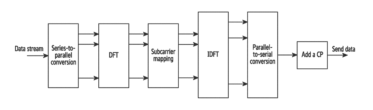
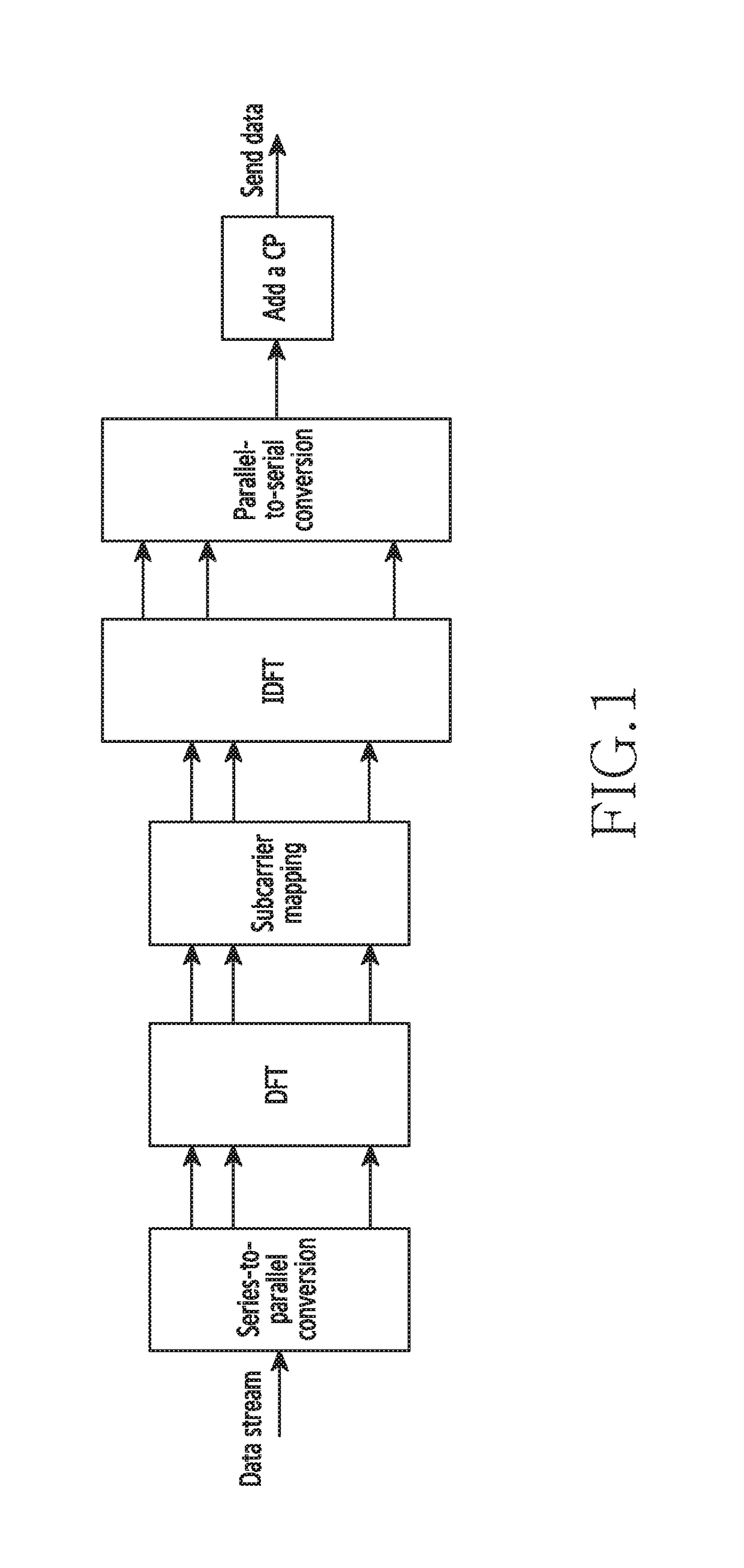
[0081]In this embodiment, to describe the method steps more conveniently, the structure of a transmitter for transmitting a terminal signal will be introduced by specific parameters...

embodiment 2

[0132]Correspondingly, referring to FIG. 12, the present disclosure also provides an embodiment of a multi-terminal information receiving method based on grid mapping, comprising the following steps of:

[0133]S21: configuring a grid mapping pattern, and transmitting the grid mapping pattern to each terminal,

[0134]S22: performing RF-to-baseband processing on received information data of each terminal, the information data being superimposed via channels; and

[0135]S23: processing the information data by a multi-terminal joint detector, and distinguishing each terminal based on the grid mapping pattern to determine the information data corresponding to each terminal.

[0136]The method further comprises: configuring a bit-level interleaving pattern and transmitting the bit-level interleaving pattern to each terminal, and distinguishing, by the multi-terminal joint detector, each terminal based on the corresponding bit-level interleaving pattern.

[0137]FIG. 13 is a block diagram of a transmi...

embodiment 3

[0175]In order to further describe the multi-terminal joint detector of Embodiment 2, the structure of a multi-terminal joint detector applicable to the present disclosure and a corresponding detection algorithm will be introduced in this embodiment. The structure of a multi-terminal joint detector in this embodiment is as shown in FIG. 16.

[0176]In FIG. 16, the multi-terminal detector receives signals from a multiple of terminals, which are polluted by channels and noise and superposed, and prior information from a multiple of channel decoders, which is composed of a multiple of terminal information estimations; and outputs posterior information of a multiple of pieces of terminal information, for being used in the subsequent decoding and other steps.

[0177]The multi-terminal detector of the present disclosure is applicable to single-carrier interleave-grid multiple access of the present disclosure, and also applicable to interleave-grid multiple access based on the SC-FDMA waveform....


PUM


Abstract

The present disclosure relates to a pre-5th-Generation (5G) or 5G communication system to be provided for supporting higher data rates Beyond 4th-Generation (4G) communication system such as Long Term Evolution (LTE). Methods and apparatuses for grid mapping are described. A method for operating a base station comprises configuring grid mapping patterns for a plurality of terminals, transmitting, to the plurality of terminals, the grid mapping patterns, receiving, from the plurality of terminals, information on which a grid mapping is performed based on the grid mapping patterns, and identifying data of the information corresponding to each of the plurality of terminals based on the grid mapping patterns. Therefore, the terminal can hold a low peak-to-average power ratio, and the power consumption can be effectively saved. The base station can complete signal detection in a moderate detection complexity by multi-terminal joint detection. The detection complexity and the performance are balanced.

Description

CROSS-REFERENCE TO RELATED APPLICATIONS AND CLAIM OF PRIORITY[0001]This application is related to and claims priority to Chinese Application No. 201610697575.2 filed on Aug. 19, 2016, the contents of which are incorporated herein by reference.TECHNICAL FIELD[0002]The present disclosure relates to a wireless communication system, and more specifically, relates to methods and apparatuses for grid mapping in a wireless communication system.BACKGROUND ART[0003]To meet the demand for wireless data traffic having increased since deployment of 4th generation (4G) communication systems, efforts have been made to develop an improved 5th generation (5G) or pre-5G communication system. Therefore, the 5G or pre-5G communication system is also called a ‘Beyond 4G Network’ or a ‘Post LTE System’.[0004]The 5G communication system is considered to be implemented in higher frequency (mmWave) bands, e.g., 60 GHz bands, so as to accomplish higher data rates. To decrease propagation loss of the radio w...

Claims


Application Information

Patent Timeline
Patent Type & Authority Applications(United States)
IPC IPC(8): H03M13/27H04W64/00H04W84/04H04W88/06
CPCH03M13/271H04W88/06H04W84/045H04W64/006H04L27/2602H04L27/2614H04L27/2647H03M13/27H04L5/0048H04L5/005
Inventor QIAN, CHENXIONG, QIYU, BINFU, JINGXING
Owner SAMSUNG ELECTRONICS CO LTD
Why Eureka
Try Eureka