
Novel cervical vertebra tractor

a cervical vertebra tractor and tractor body technology, applied in the field of medical and health products, can solve the problems of not meeting the requirements of users, and achieve the effects of enhancing the support strength of the cervical vertebra, preventing deformation, and effective traction

Inactive Publication Date: 2018-03-01
HENGSHUI LEAMAI MEDICAL INSTR CO LTD
View PDF3 Cites 1 Cited by
  • Summary
  • Abstract
  • Description
  • Claims
  • Application Information

AI Technical Summary

Benefits of technology

The cervical vertebra tractor is designed to be adjustable to different body sizes and has a separable structure. A cervical collar and traction belt are assembled through a Velcro before use. The cervical collar support strengthens the cervical vertebra and prevents deformation. Users can choose inflation means based on their habits, and the traction belt conforms to the physiological curve of the human body for effective traction.

Problems solved by technology

Moreover, the rear side of the traction belt, when inflated, cannot form a physiological curve angle, which does not conform to the principle of human cervical vertebra recovery and cannot achieve an effective traction of the cervical vertebra, thus being failed to meet the users' requirements.

Method used


Image

  • Novel cervical vertebra tractor
  • Novel cervical vertebra tractor
  • Novel cervical vertebra tractor

Examples


first embodiment

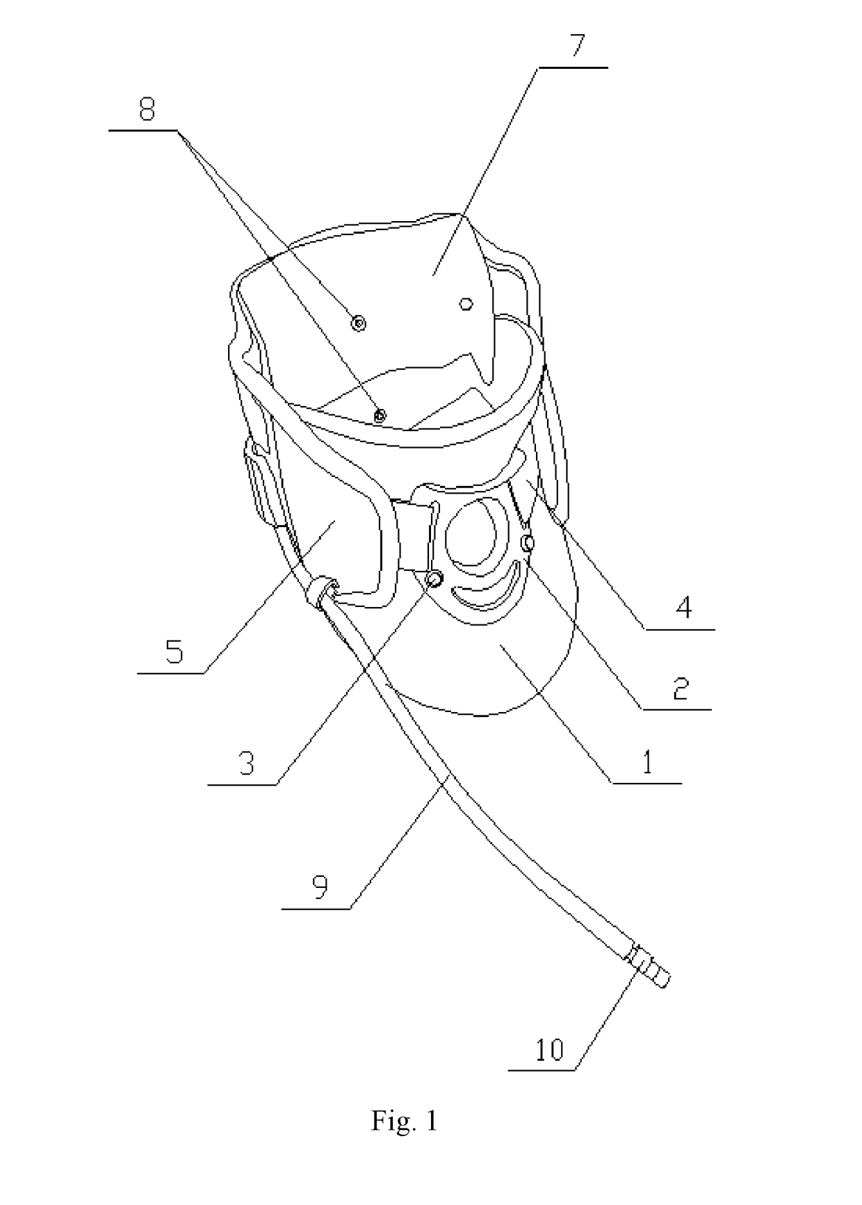
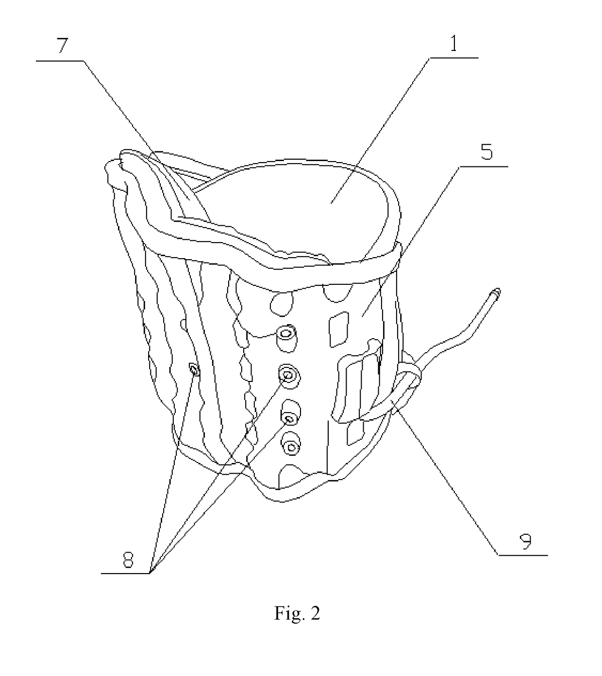
[0019]As shown in FIGS. 1-6, the present embodiment adopts a technical solution as follows. It includes a cervical collar 1, a cervical collar support 2, a plastic rivet 3, Velcro hook sides 4, a traction belt 5, Velcro loop sides 6, a first cushion 7, vent holes 8, an inflation tube 9, a connector 10, a hand press ball 11, and an air stopping knob 12. The cervical collar 1 is provided with the cervical collar support 2 at a middle portion at a front end thereof, and the cervical collar support 2 is fastened to the cervical collar 1 through a plastic rivet 3. The Velcro hook sides 4 are attached respectively to left and right ends of the cervical collar support 2. The two Velcro hook sides 4 are fastened respectively to two ends of an outer side of the cervical collar 1. The Velcro loop sides 6 are respectively provided at two ends of an inner side of the traction belt 5. The Velcro loop sides 6 at the two ends of the traction belt 5 are adhered respectively to the Velcro hook sides...

second embodiment

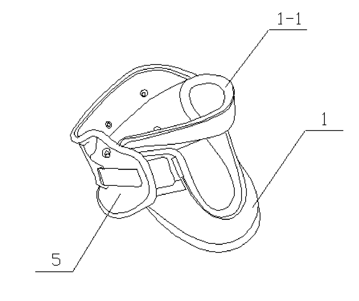
[0021]As shown in FIGS. 7-9, this embodiment differs from the first embodiment as follows. The cervical collar 1 is a plastic cervical collar provided with a second cushion 1-1 on its inner side in a region that is to contact the human body. A plastic support 5-1 is provided on the outer side of the traction belt 5 for enhancing the supporting strength of the traction belt. The other end of the inflation tube 9 is connected to a connection port 13-1 in the air pump 13 through the connector 10. An extension tube 13-2 is provided inside the air pump 13. A connector locking means 13-3 is mounted on the lower side of the air pump 13. Other components and connection relationships are the same as those in the first embodiment.

[0022]In this embodiment, a separable structure design is adopted in which the cervical collar and the traction belt are assembled through a Velcro before use, so that the cervical vertebra tractor is adjustable to different body sizes of the users. By providing the ...


PUM


Abstract

The present utility model discloses a novel cervical vertebra tractor in which Velcro hook sides are attached respectively to left and right ends of a cervical collar support, Velcro loop sides are provided respectively at two ends of an inner side of a traction belt, and the Velcro loop sides and the Velcro hook sides are adhered to each other. A first cushion is provided at the middle portion of the inner side of the traction belt. Multiple vent holes are provided at the middle portion of the traction belt. A balloon is provided inside the traction belt. One end of an inflation tube is connected to the balloon, and the other end of the inflation tube is provided with a connector.

Description

FIELD OF THE INVENTION[0001]The present utility model relates to the technical field of medical and health products, and particularly to a novel cervical vertebra tractor.BACKGROUND OF THE INVENTION[0002]Therapies for cervical spondylosis include non-surgical treatments and surgical treatments. Among the non-surgical treatments, traction is a prevailing means of alleviating the symptoms in the treatment of cervical spondylosis. Effective traction can eliminate the muscle spasm in the neck, alleviate the pains, increase the intervertebral space and the intervertebral foramen, facilitate the stabilization of protruded nucleus pulposus and annulus fibrosis, alleviate and relieve the nerve root compression and stimulation, promote the absorption of nerve root edema, relieve the compression of the vertebral artery by the vertebra, promote the blood circulation, facilitate the regression of local congestion, swelling, and hyperplasia, relax the adhesive joint capsules, ameliorate and reco...

Claims


Application Information

Patent Timeline
IPC IPC(8): A61F5/055A61F5/058
CPCA61F5/05816A61F5/055
Inventor TIAN, YING
Owner HENGSHUI LEAMAI MEDICAL INSTR CO LTD
Learn More