Electromagnetic relay

a technology of electromagnetism and relay, applied in the field of electromagnetism relay, can solve the problems of reducing the dielectric strength in the space between and difficulty in interrupting the electric arc, and achieve the effect of increasing the opening speed of fixed and movable contacts

Active Publication Date: 2018-03-01
PANASONIC INTELLECTUAL PROPERTY MANAGEMENT CO LTD
View PDF11 Cites 20 Cited by
  • Summary
  • Abstract
  • Description
  • Claims
  • Application Information

AI Technical Summary

Benefits of technology

[0005]The present disclosure has been achieved in view of the above circumstances, and an object thereof i

Problems solved by technology

It is accordingly difficult to interrupt the electric arc because dielec

Method used


Image

  • Electromagnetic relay
  • Electromagnetic relay
  • Electromagnetic relay

Examples


embodiment 1

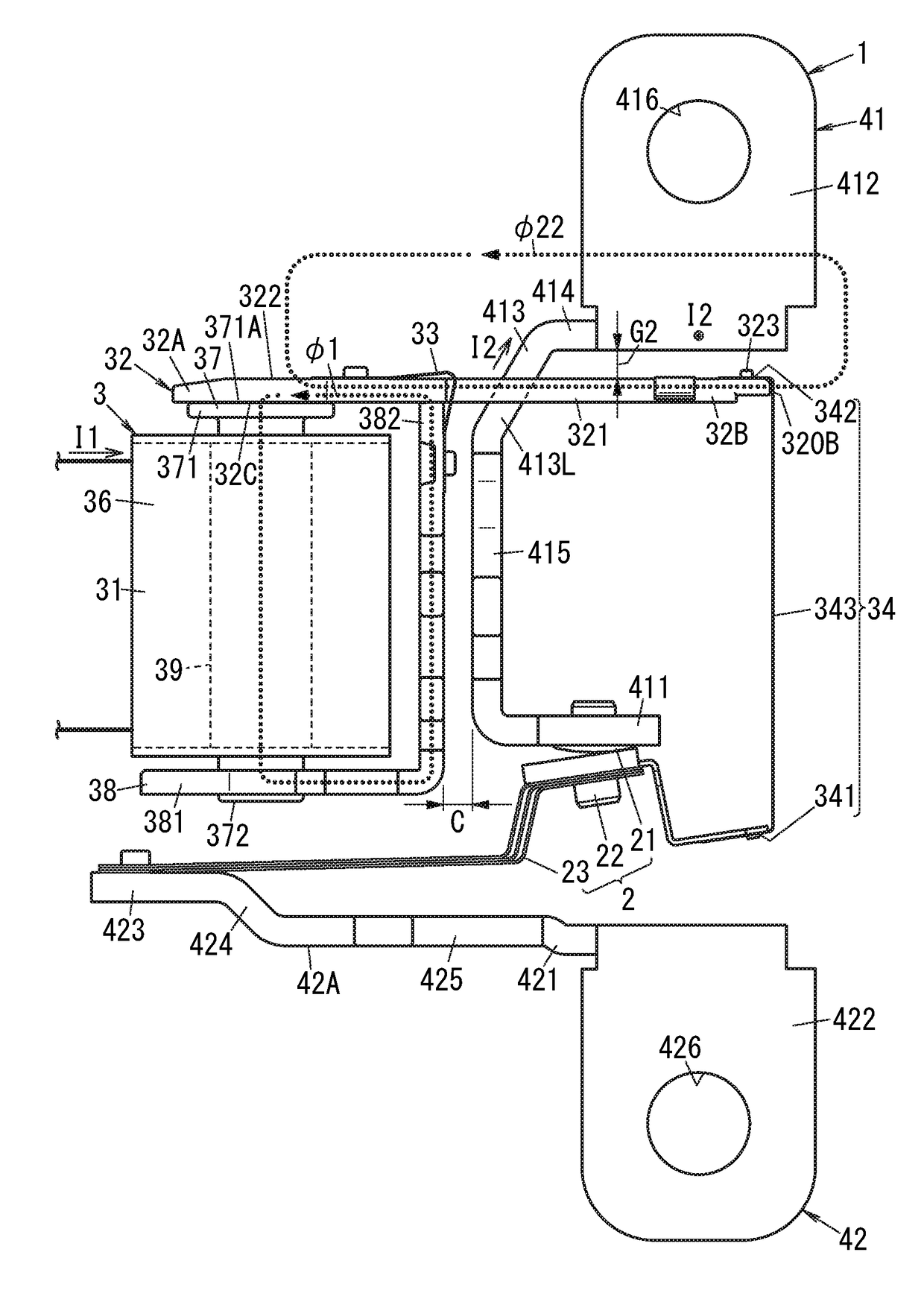
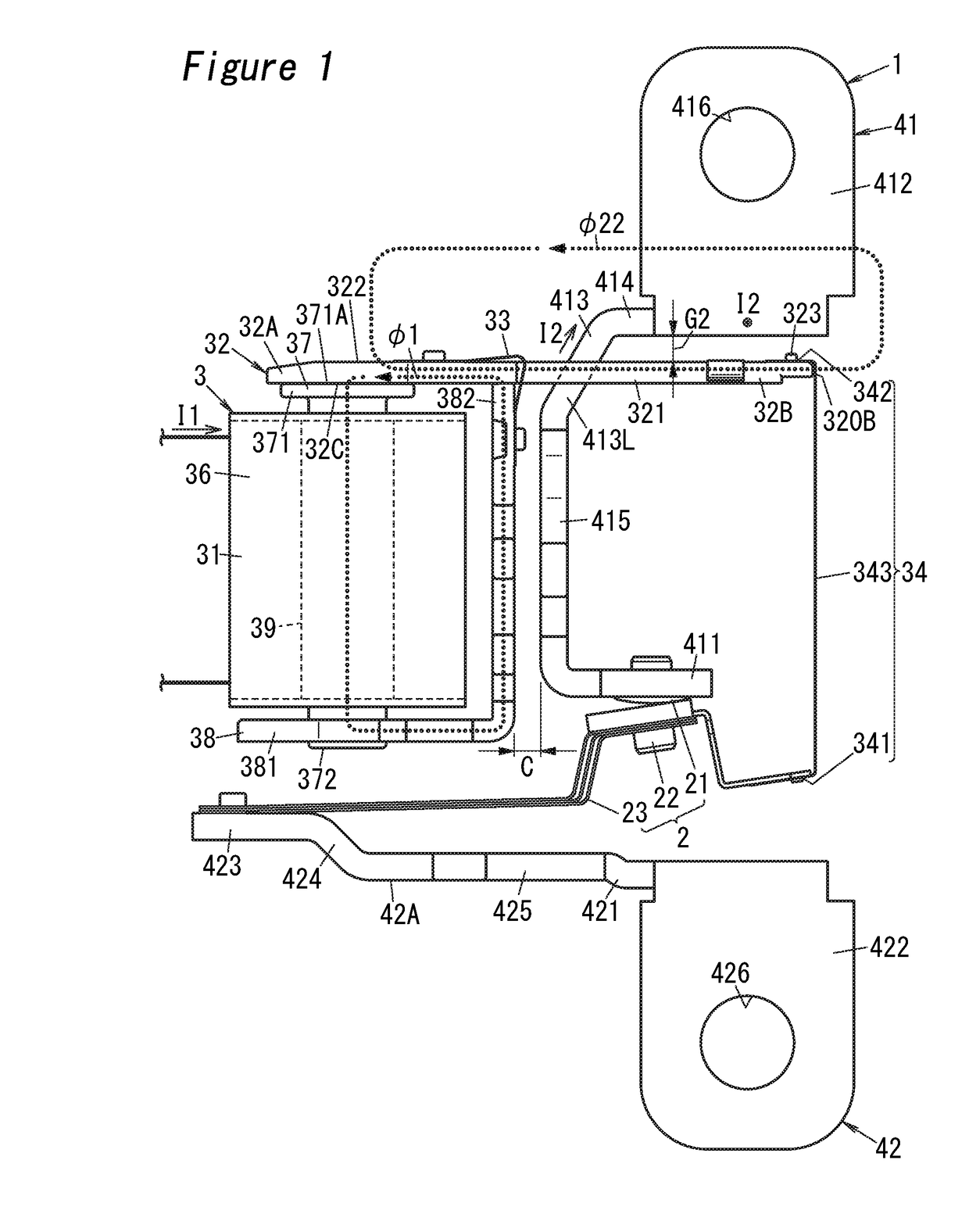
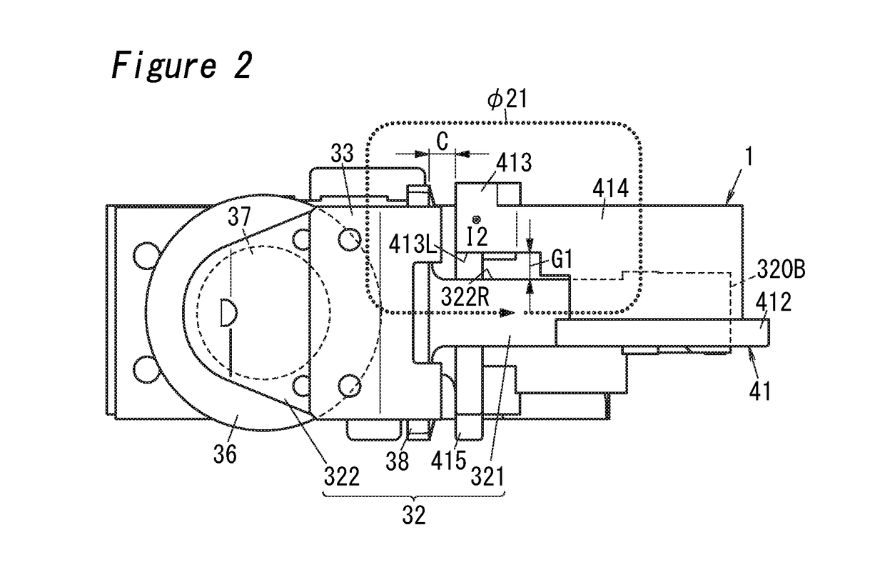
[0025]As shown in FIGS. 1 to 6, an electromagnetic relay according to Embodiment 1 preferably includes a contact mechanism 2, an actuator 3, a fixed terminal 41 and a movable terminal 42.

[0026]The contact mechanism 2 preferably includes a fixed contact 21, a movable contact 22 and a contact spring 23. The fixed terminal 41 is provided with the fixed contact 21. The movable contact 21 makes or breaks a connection with the fixed contact 21. In other words, the movable contact 22 is to come into contact with the fixed contact 21, and separate therefrom. The contact spring 23 movably supports the movable contact 22 so that the fixed and movable contacts 21 and 22 are forced together and apart.

[0027]The actuator 3 is configured to force the movable contact 22 to touch the fixed contact 21 and separate therefrom. The actuator 3 preferably includes an electromagnet device 31, an armature 32, a hinge spring 33 and a card 34.

[0028]The electromagnet device 31 is configured to drive the armatu...

embodiment 2

[0070]As shown in FIGS. 7 to 9, an electromagnetic relay 1a according to Embodiment 2 differs from the electromagnetic relay 1 according to Embodiment 1 (see FIG. 1) in that the effect of first magnetic flux φ3 generated in an armature 32 by coil current I3 is reduced at one place of a fixed terminal 43 (crossing piece 433). Note that like kind elements are assigned the same reference numerals as depicted in Embodiment 1, and are not explained herein.

[0071]In Embodiment 2, the fixed terminal 43 is preferably provided around the armature 32 so as to cross the armature 32 as seen from only one direction (a direction perpendicular to the sheet of FIG. 7, a vertical direction in FIG. 8) to a lengthwise direction (first direction) of the armature 32. Note that explanation of functions, similar to the fixed terminal 41 (see FIG. 1) in Embodiment 1, of the fixed terminal 43 in Embodiment 2 is omitted.

[0072]The fixed terminal 43 preferably includes an attachment piece 431, a terminal piece ...


PUM


Abstract

An electromagnetic relay includes an electromagnet device, an armature and a fixed terminal. By coil current through a coil, the electromagnet device generates first magnetic flux that forces the armature and the electromagnet device together or apart in a first end in a first direction of the armature. The armature is connected with a movable contact at a second end of the first direction and forces the movable contact and a fixed contact together or apart according to coil current. The fixed terminal is electrically connected with the fixed contact, and provided around the armature so as to cross the armature as seen from a second direction perpendicular to the first direction with the armature closing the fixed and movable contacts. Electric current through the fixed terminal generates a second magnetic flux in the armature, a direction of which is opposite to that of the first magnetic flux.

Description

CROSS REFERENCE TO RELATED APPLICATION[0001]This application claims the benefit and priority of Japanese Patent Application No. 2016-169589, filed on Aug. 31, 2016, the entire contents of which is incorporated herein by reference.TECHNICAL FIELD[0002]The present disclosure relates to an electromagnetic relay.BACKGROUND ART[0003]In the configuration of a related electromagnetic relay, it has been known to force fixed and movable contacts together or apart by magnetic force of a driving unit (electromagnetic device) (for example, JP 2015-216052 A (hereinafter referred to as “Document 1”)). The electromagnetic device described in Document 1 includes a fixed contact, a movable contact, the driving unit that generates magnetic flux according to coil current, and an armature that is driven through the driving unit. In the electromagnetic device, the armature is connected with the movable contact through a card, and driven through the driving unit, thereby rotating toward an iron core of t...

Claims


Application Information

Patent Timeline
IPC IPC(8): H01H51/28H01H51/06H01H50/30H01H51/30H01H50/32H01H51/36
CPCH01H51/28H01H51/06H01H50/30H01H50/443H01H50/321H01H51/36H01H51/30H01H50/16H01H50/54H01H50/64H01H9/443H01H50/14H01H50/38H01H50/42H01H50/642
Inventor ITO, MASAHIRO
Owner PANASONIC INTELLECTUAL PROPERTY MANAGEMENT CO LTD
Why Eureka
Try Eureka