System and method for capacitor fault energy interruption in adjustable speed drives

a technology of adjustable speed drive and fault energy interruption, which is applied in the direction of electric motor control, dynamo-electric converter control, ac motor stopper, etc., can solve the problems of short non-short circuit across a capacitor, and insufficient protection of asd circuits

Active Publication Date: 2018-03-01
EATON INTELLIGENT POWER LTD
View PDF5 Cites 12 Cited by
  • Summary
  • Abstract
  • Description
  • Claims
  • Application Information

AI Technical Summary

Benefits of technology

[0006]Embodiments of the present invention provide a system and method for minimizing and interrupting capacitor fault energy in ASD circuits to prevent DC link electrolytic capacitors from catastrophic failures by a fault condition, such as a capacitor short circuit.

Problems solved by technology

While the above described architecture of the ASD circuit 10 allows for efficient operation thereof, the ASD circuit lacks sufficient protection against various internal and external fault conditions that could damage ASD circuit.
Breakdown of components tests on the ASD circuit, such as those performed to determine compliance of the circuit under Standard UL61800-5-1, may also cause a short circuit across a capacitor.
In any case, a short circuit across a capacitor in an ASD circuit will cause the ASD circuit to fail and, if power is allowed to continue to flow to the capacitor bank when one capacitor has a short circuit, an overvoltage condition will exist on the non-shorted capacitor.
This overvoltage condition may, in electrolytic capacitors, cause the non-shorted capacitor to catch on fire and possibly explode.
However, the resistors 40 are not adequate to fully protect the capacitors, as the resistors cannot prevent power from continuing to flow to a shorted capacitor in DC capacitor bank 24.
The overvoltage condition on the non-shorted capacitor will cause ASD circuit 10 to be damaged, such that the damaged ASD circuit 10 will not be useable and a user will have to make costly repairs to the ASD circuit or replace the ASD circuit.
The user will incur additional economic losses during the downtime period when ASD circuit 10 is not in use.

Method used


Image

  • System and method for capacitor fault energy interruption in adjustable speed drives
  • System and method for capacitor fault energy interruption in adjustable speed drives
  • System and method for capacitor fault energy interruption in adjustable speed drives

Examples


first embodiment

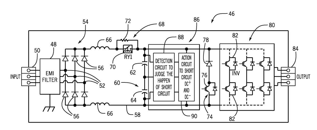
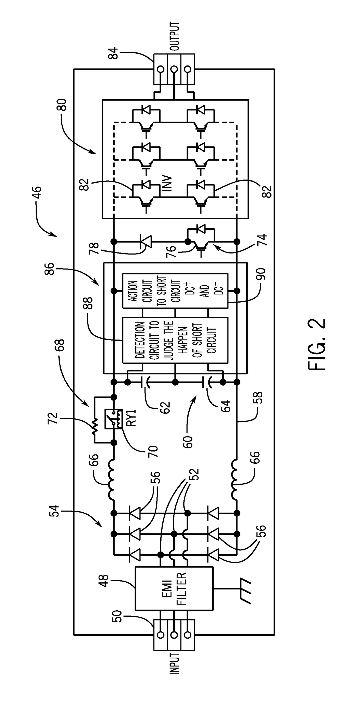
[0024]Referring now to FIGS. 3 and 4 and to FIGS. 5-7, various embodiments of the detection circuit 88 and the action circuit 90, respectively, that might be incorporated into or utilized by ASD circuit 46 are shown. Referring first to FIGS. 3 and 4, embodiments of different detection circuits 88 that might be incorporated into or utilized by ASD circuit 46 are shown. In a first embodiment, and as shown in FIG. 3, the detection circuit 88 may include a pair of opto-couplers 92 and associated diodes 94 and voltage-sharing resistors 96—with each of the resistors 96 being positioned in series with its respective diode 94 and opto-coupler 92. The opto-couplers 92 function to selectively generate and transmit signals based on a condition of the capacitors 62, 64, with each of the opto-couplers 92 having a known construction that includes an opaque package that houses a light source that converts electrical input signal into light (e.g., LED), a sensor that detects incoming light and gene...

second embodiment

[0026]In a second embodiment, and as shown in FIG. 4, the detection circuit 88 may include a voltage sampling or sensing circuit 98 and an associated logic circuit 100. The voltage sampling circuit 98 includes voltage sensors 102 positioned on capacitor bank 60 that measure the voltage across capacitor 62. As shown in FIG. 4, according to one embodiment, voltage sampling circuit 98 may also include an optional voltage sensor 104 so that the voltage across capacitor 64 may be measured as well. Voltage sampling circuit 98 may include additional sensors depending on the number of capacitors in capacitor bank 60.

[0027]In detecting a short circuit in capacitor bank 60, logic circuit 100 compares the voltage across capacitor 62 received from voltage sampling circuit 98 to a voltage threshold or limit such as, for example, an overvoltage threshold or an undervoltage threshold. If the voltage across capacitor 62 crosses or passes the voltage threshold, logic circuit 100 detects a shorted ca...

third embodiment

[0031]In a third embodiment, and as shown in FIG. 7, the action circuit 90 may include a logic control circuit 116 operably connected to the inverter 80 to control switching of the IGBTs 82 therein. The logic circuit 116 is in operable communication with detection circuit 88 to receive input signals (i.e., action signals) therefrom indicative of a condition of the capacitors 62, 64. When the logic circuit 116 receives an action signal from detection circuit 88, the logic circuit 116 transmits gating signals to two IGBTs 82 arranged in series on a same leg 118 of the inverter 80 at the same time so as to cause the two IGBTs 82 to turn on simultaneously—thereby short circuiting the DC link 58. While FIG. 7 illustrates that logic circuit 116 is operably connected to just the two IGBTs 82 in leg 118 to control switching thereof, it is recognized that the IGBTs 82 on two of the inverter legs 118 or all three of the inverter legs 118 could be turned on at the same time to short circuit th...


PUM


Abstract

An adjustable speed drive (ASD) circuit includes a rectifier bridge to convert an AC power input to a DC power, a DC link coupled to the rectifier bridge to receive the DC power, a DC link capacitor bank comprising at least first and second capacitors connected to the DC link, each capacitor having a capacitor voltage thereacross, and a protection circuit including a detection circuit configured to detect a short circuit on one or more of the first and second capacitors of the DC link capacitor bank and generate an action signal upon detection of a short circuit on one or more of the first and second capacitors of the DC link capacitor bank. The ASD circuit also includes an action circuit in operable communication with the detection circuit and configured to cause a short circuit across the DC link upon receiving the action signal from the detection circuit.

Description

BACKGROUND OF THE INVENTION[0001]The present invention relates generally to adjustable speed drive (ASD) circuits and, more particularly, to a system and method for minimizing and interrupting capacitor fault energy in ASD circuits to protect the electrolytic DC link capacitors from being damaged by a fault condition.[0002]One type of system commonly used in industry that performs power conversion is an ASD circuit, also known as a variable frequency drive (VFD) circuit. An ASD is an industrial control device that provides for variable frequency, variable voltage operation of a driven system, such as an AC induction motor. A typical ASD circuit 10 is illustrated in FIG. 1. ASD or VFD circuit 10 includes an electromagnetic interference (EMI) filter 12 provided between a drive input 14 and input rectifier terminals 16. The terminals are connected to a rectifier bridge 18 that converts an AC input power provided at drive input 14 into a DC power, with the rectifier bridge 18 being in t...

Claims


Application Information

Patent Timeline
Patent Type & Authority Applications(United States)
IPC IPC(8): H02P29/024H02P27/08H02K17/30
CPCH02P29/024H02K17/30H02P27/08H02P3/22H02P2201/03H02M1/32H02M5/458H02H7/1216H02P29/0241H02M1/007H02M1/322
Inventor TAO, TONYLI, XIAOLINGLI, HUAQIANG
Owner EATON INTELLIGENT POWER LTD
Why Eureka
Try Eureka