Methods and systems for computer-aided surgery using intra-operative video acquired by a free moving camera

Active Publication Date: 2018-03-15
UNIVE DE COIMBRA
View PDF14 Cites 61 Cited by
  • Summary
  • Abstract
  • Description
  • Claims
  • Application Information

AI Technical Summary

Benefits of technology

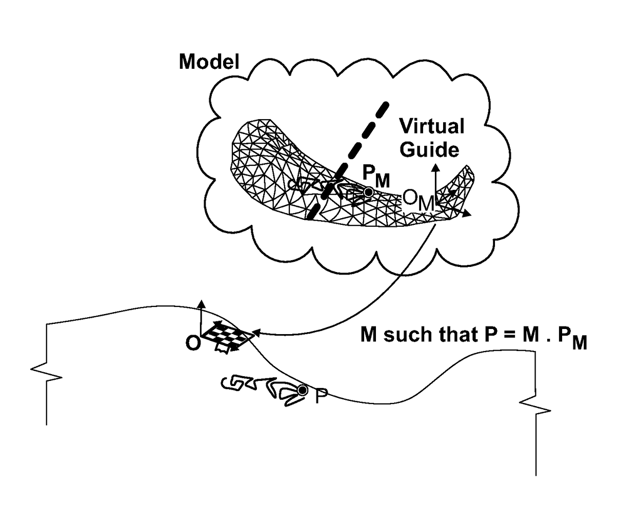
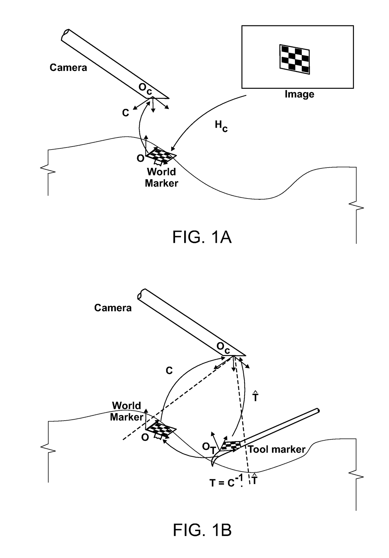
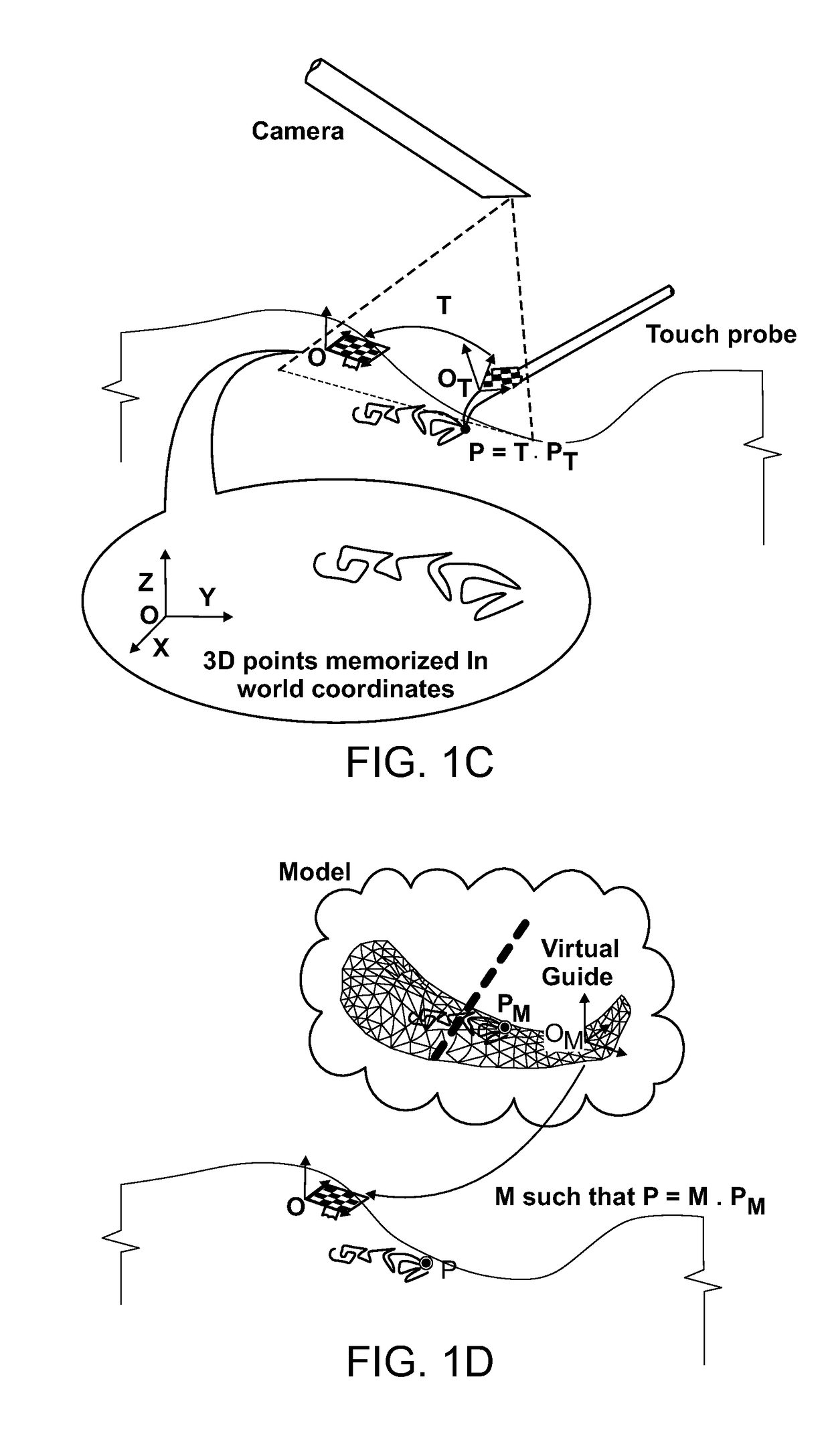
[0012]The concept, henceforth referred as Visual-Tracking Inside the Anatomical Cavity (VTIAC), introduces three main differences from other embodiments of OT/ET in the context of computer-aided surgery: First, the global world reference frame, instead of being the coordinate frame of the external base station, it is the system of coordinates of a marker that is rigidly attached to the anatomy of interest (e.g. bone surface). This marker, referred to herein as World Marker or WM, serves as absolute reference such that

Problems solved by technology

The use of plane homographies in clinical setups has been relatively scarce.
Moreover, while in MicronTracker® the base station is the external stereo setup, which raises the issues about line of sight inherent to conventional OT, in VTIAC, measurements are carried out with respect to the WM that is rigidly attached to the surface inside the articular joint or anatomical cavity.
Moreover, measurements are typically represented in camera coordinates, which means that it is not possible to relate or integrate information across frames because the laparoscope is in constant motion.
Unfortunately, the application to computer-aided surgery is not straightforward because the close-range operation requires cameras with a wide FOV that typically introduce very strong radial distortion.
The distortion hinders correct de

Method used


Image

  • Methods and systems for computer-aided surgery using intra-operative video acquired by a free moving camera
  • Methods and systems for computer-aided surgery using intra-operative video acquired by a free moving camera
  • Methods and systems for computer-aided surgery using intra-operative video acquired by a free moving camera

Examples


Example

1. Introduction

[0052]It should be understood that, although an illustrative implementation of one or more embodiments are provided below, the various specific embodiments may be implemented using any number of techniques known by persons of ordinary skill in the art. The disclosure should in no way be limited to the illustrative embodiments, drawings, and / or techniques illustrated below, including the exemplary designs and implementations illustrated and described herein.

[0053]One or more embodiments disclosed herein applies to camera-guided orthopedic MIS procedures, namely arthroscopy, that is used as illustrative example throughout most of the description. However, the application of the presently disclosed embodiments can include other surgical procedures and clinical specialties where the operating field comprises rigid, non-deformable parts and surfaces. The application of the disclosed embodiments requires a camera system for visualizing the anatomical scene that might alread...


PUM


Abstract

Disclosed is a concept for computer-assisted procedures of surgery and diagnosis that target rigid, non-deformable anatomical parts such as bone, tissue, or teeth. The disclosure describes attaching small visual markers to instruments and anatomy of interest (e.g. bone surface), with each marker having a printed known pattern for detection and unique identification in images acquired by a free-moving camera, and a geometry that enables estimating its rotation and translation with respect to the camera using solely image processing techniques.

Description

CROSS-REFERENCE TO RELATED APPLICATIONS[0001]This patent application claims the benefit of U.S. Provisional Patent Application Ser. No. 62 / 138,529, filed on Mar. 26, 2015 and titled “Methods and Systems for Computer-Aided Navigation in Surgical Procedures”, and U.S. Provisional Patent Application Ser. No. 62 / 255,513, filed on Nov. 15, 2015 and titled “Methods and Systems for Computer-Aided Navigation in Surgical Procedures”, both of which are hereby incorporated by reference in their entireties.STATEMENT REGARDING FEDERALLY SPONSORED RESEARCH OR DEVELOPMENT[0002]Not applicable.FIELD[0003]The disclosure generally relates to the field of computer-aided surgery, and in particular, but not by way of limitation, the disclosed embodiments refer to computer aided-navigation in camera guided procedures of surgery and diagnosis in anatomical regions with rigid tissues such as bone, which includes arthroscopy of knee, hip, or shoulder, and open surgery in orthopedics and dentistry in which ca...

Claims


Application Information

Patent Timeline
IPC IPC(8): A61B34/20A61B34/00A61B34/10A61B34/30A61B90/00H04N13/02G06T7/50G06T7/62G06T7/73G06T7/80G06T19/00H04N13/221
CPCA61B34/20A61B34/25A61B34/10A61B34/30A61B90/361H04N13/0221G06T7/50G06T7/62G06T7/73G06T7/85H04N13/0246G06T19/006A61B2090/3937A61B2090/3991A61B2090/365A61B2034/2065A61B2034/2057A61B2090/3983A61B2090/3945A61B2034/301A61B2034/302G06T2207/30208G06T2207/30244G06T2219/004A61B2034/2055G06F3/0321G16H50/50H04N13/221H04N13/246G16H30/40G16H20/40G16H20/30G16H30/20
Inventor DE ALMEIDA BARRETO, JOAO PEDRO
Owner UNIVE DE COIMBRA
Why Eureka
Try Eureka