Rotational flow atomizing precombustion type heavy oil burner

A heavy oil combustion and pre-combustion technology, which is applied in the direction of burners, combustion methods, and controlled combustion, can solve the problem of high concentration and achieve the effects of less investment, significant energy saving and environmental protection benefits, and compact layout

Inactive Publication Date: 2016-02-24
CENT SOUTH UNIV
View PDF9 Cites 1 Cited by
  • Summary
  • Abstract
  • Description
  • Claims
  • Application Information

AI Technical Summary

Problems solved by technology

[0005] In order to overcome the traditional sleeve-type high-pressure burner to complete all the atomization process only by the turbulence of the high-speed air flow ejected from the Laval nozzle, all the oil atomization and combustion reactions are completed in the area near the exit of the Laval nozzle. To solve the problems of high concentration of carbon black, carbon monoxide and nitrogen oxides, the present invention designs a kind of "oil pipe set in the tapered nozzle, the tapered nozzle is connected with the burner brick in the shape of a circular table, and multiple air supply pipes are used" etc. Structural features, technical features such as "oil swirl secondary atomization, oil mist swirl pre-combustion", multiple technologies such as "simple structure, convenient installation, reliable performance, low nitrogen oxide emission concentration, high combustion efficiency and high energy efficiency" Advantageous swirl atomization pre-combustion heavy oil burner

Method used


Image

  • Rotational flow atomizing precombustion type heavy oil burner
  • Rotational flow atomizing precombustion type heavy oil burner
  • Rotational flow atomizing precombustion type heavy oil burner

Examples


Embodiment Construction

[0013] The invention will be further described below in conjunction with the accompanying drawings.

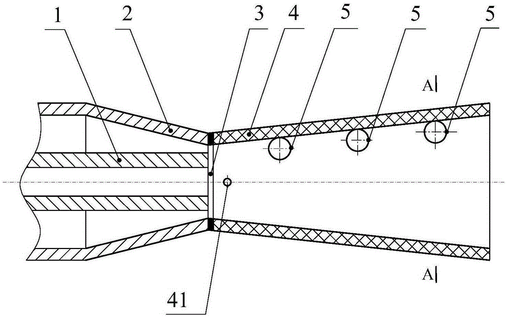
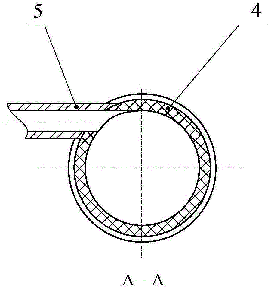
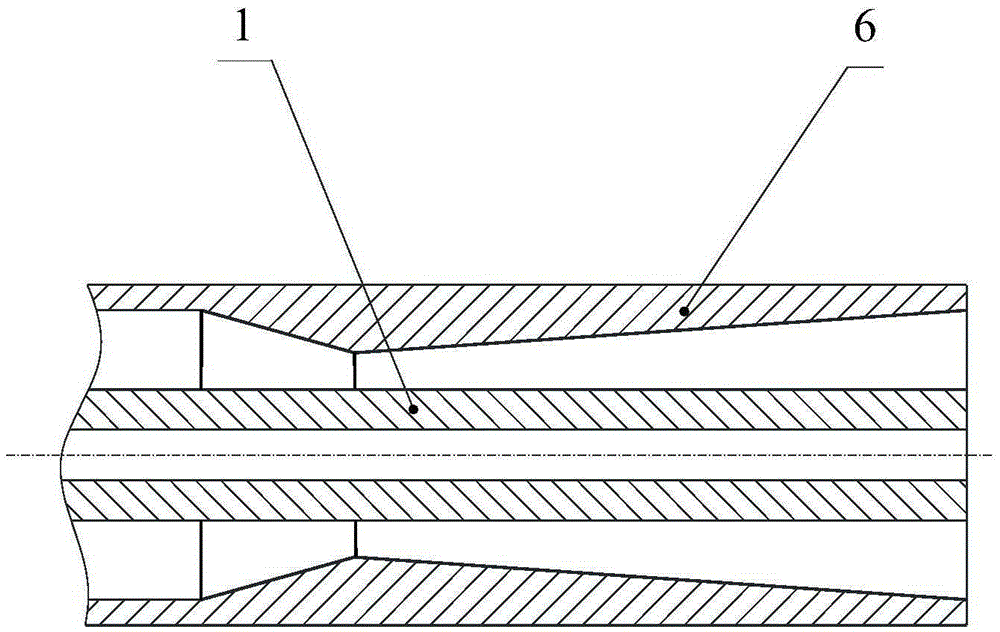
[0014] as attached figure 1 And attached figure 2 As shown, the swirling atomization pre-combustion heavy oil burner mainly includes oil pipe 1, tapered nozzle pipe 2, gasket 3, burner brick 4 and numerous air supply pipes 5. The air flow channel of the supplementary air pipe 5 and the oil passage of the oil pipe 1 are all circular channels with equal area, and the pipe material of the oil pipe 1 and the pipe material of the air supplement pipe 5 are all metal materials. The side wall of the burner brick 4 is provided with an ignition hole 41 . Burner brick 4, washer 3, tapering nozzle 2 and oil pipe 1 have four central axes collinear, oil pipe 1 is covered with tapering nozzle 2, and the exit end face of tapering nozzle 2 is coplanar with oil pipe 1 outlet end face. The gasket 3 is arranged between the outlet end face of the tapering nozzle 2 and the inlet end face of th...


PUM


Abstract

The invention discloses a rotational flow atomizing precombustion type heavy oil burner. The rotational flow atomizing precombustion type heavy oil burner mainly comprises a reducing spray pipe, a washer, a burner block and a plurality of air supplement pipes. The center axes of the burner block, the washer, the reducing spray pipe and an oil pipe are collinear. The reducing spray pipe is installed outside the oil pipe in a sleeving mode. The outlet end faces of the reducing spray pipe and the oil pipe are coplanar. The washer is arranged between the reducing spray pipe and the burner block. The center axes of the air supplement pipes are parallel and located on the same plane. The plane where the air supplement pipes are located is perpendicular to the vertical cross section passing through the center axis of the burner block. The horizontal cross section passing through the center axis of the burner block obliquely intersects with the plane where the air supplement pipes are located. Compressed air is supplemented through the air supplement pipes, and a gas-oil mixture in the burner block is made to flow spirally. The rotational flow atomizing precombustion type heavy oil burner can be used for energy-saving technical modification of oil-fired industrial furnace combustion systems. The application shows that the rotational flow atomizing precombustion type heavy oil burner is compact in layout, small in investment and free of coking blocking; the combustion efficiency is 99%, the energy saving rate is 5%-10%, and the requirement of the integrated emission standard of air pollutants of GB16297-1996 for the flue gas pollutant emission is met.

Description

technical field [0001] The invention relates to a swirl atomization pre-combustion type heavy oil burner which mainly burns difficult-to-atomize liquid fuel and is based on the principle of swirl secondary atomization and swirl pre-combustion, and is mainly suitable for use in fuel oil industrial furnace combustion systems . Background technique [0002] Promoting industrial green transformation and upgrading and improving industrial energy efficiency are major measures to implement the spirit of the Third Plenary Session of the 18th CPC Central Committee and promote the construction of ecological civilization. The "Action Plan for Prevention and Control of Air Pollution" (Guo Fa [2013] No. 37) proposes that the energy consumption per unit product of new high-energy-consuming projects must reach the domestic advanced level, and the energy-using equipment must meet the first-class energy efficiency standard. "China Energy Statistical Yearbook 2013" (China Statistics Press, D...

Claims


Application Information

Patent Timeline
Patent Type & Authority Applications(China)
IPC IPC(8): F23D11/24F23D11/38F23N1/02
CPCF23D11/24F23D11/38F23N1/02
Inventor 艾治文艾元方黄淑辉周睿
Owner CENT SOUTH UNIV
Why Eureka
Try Eureka