3D printing of graphene (OXIDE) composites

Active Publication Date: 2018-03-22
SIGNIFY HLDG BV
View PDF1 Cites 5 Cited by
  • Summary
  • Abstract
  • Description
  • Claims
  • Application Information

AI Technical Summary

Benefits of technology

[0006]3D printing of conducting paths in an insulating matrix usually requires at least two filaments (assuming e.g. fused deposition modelling), one filament with an insulating material, and one filament with a dispersed metal above the percolation threshold. This invention proposes to use a material which is an insulator but can be (thermally) activated to become a conductor. Therefore, the same material can be used to print insulating and conducting paths of even insulated wires. This allows printing techniques that can print only with a single starting material to produce parts with insulating and conductive elements. Also this may greatly simplify printing 3D objects having electrical conductive tracks (incorporated in the 3D object). Especially, a solution of incorporating e.g. graphene oxide in a polymer is proposed to solve

Problems solved by technology

In 3D-printed parts where different materials are deposited together, it is very difficult to separate the components at the end of the part lifetime.
This poses especially a difficulty when this concerns electronic components and connect

Method used


Image

  • 3D printing of graphene (OXIDE) composites
  • 3D printing of graphene (OXIDE) composites
  • 3D printing of graphene (OXIDE) composites

Examples


Embodiment Construction

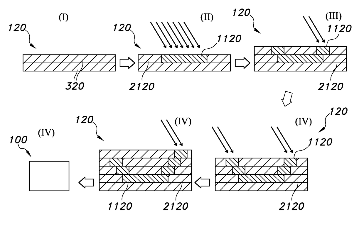
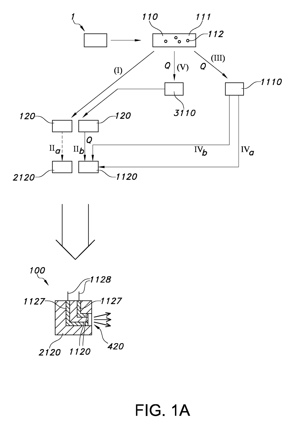
[0052]FIG. 1a schematically depicts possible process stages of a method for printing a 3D printed object 100. As indicated above, the 3D printed object 100 comprises a first type of printed material 1120 having electrically conductive properties and a second type of printed material 2120 having electrically insulating properties. To obtain such object 100, a method may be used comprising providing printable material 110, wherein the printable material 110 has electrically insulating properties and wherein the printable material 110 is convertible by heat to a material 1110,1120 having electrically conductive properties.

[0053]Hence, the method includes providing printable material 110. Subsequently, with a 3D printer 500 said printable material 110 may be printed, to generate printed material 120. During the act of generating the printed material 120 or after having generated the printed material 120, the printable material 110 or printed material 120 may be subjected to heat. Hence,...


PUM

PropertyMeasurementUnit
Electrical conductivityaaaaaaaaaa

Abstract

The invention provides a method for printing a 3D printed object (100), the 3D printed object (100) comprising a first type of printed material (1120) having electrically conductive properties and a second type of printed material (2120) having electrically insulating properties, wherein the method comprises: (I) providing printable material (110), wherein the printable material (110) has electrically insulating properties and wherein the printable material (110) is convertible by heat to a material (1110,1120) having electrically conductive properties; (II) printing with a 3D printer (500) said printable material (110) to generate printed material (120); and (III) subjecting to heat part of the printed material (120) after deposition; to provide said 3D printed object (100).

Description

FIELD OF THE INVENTION[0001]The invention relates to a method for the production of a 3D printed object. The invention also relates to such object per se, for instance obtainable with such method. The invention further relates to a 3D printer, which may for instance be used in such method for the production of a 3D printed object.BACKGROUND OF THE INVENTION[0002]Additive technologies wherein a material is incorporated in an object made via such technology are known in the art. US2013303002, for instance describes a three-dimensional interconnect structure for micro-electronic devices and a method for producing such an interconnect structure. The method comprises a step wherein a backbone structure is manufactured using an additive layer-wise manufacturing process. The backbone structure comprises a three-dimensional cladding skeleton and a support structure. The cladding skeleton comprises layered freeform skeleton parts that will form the electric interconnections between the elect...

Claims


Application Information

Patent Timeline
IPC IPC(8): B29C64/153B29C64/118B33Y10/00B33Y70/00
CPCB29C64/153B29C64/118B33Y10/00B33Y70/00B29K2507/04B29K2995/0005B29C64/106
Inventor GIESBERS, ADRIANUS JOHANNES MARIAKLOOTWIJK, JOHAN HENDRIKBALKENENDE, ABRAHAM RUDOLFTALGORN, ELISE CLAUDE VALENTINE
Owner SIGNIFY HLDG BV
Why Eureka
Try Eureka