Implant and method for producing implant
- Summary
- Abstract
- Description
- Claims
- Application Information
AI Technical Summary
Benefits of technology
Problems solved by technology
Method used
Image

Examples
first embodiment
1. First Embodiment
1-1. General Configuration
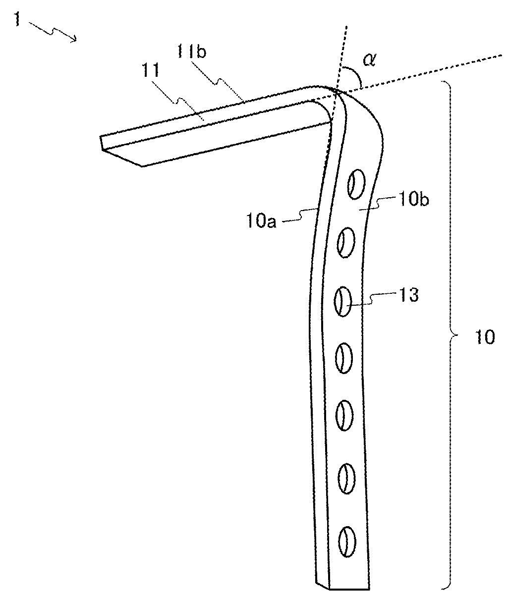
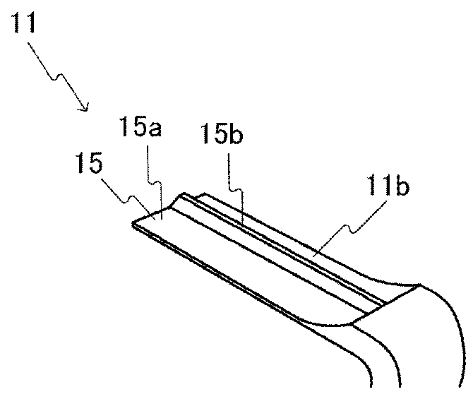
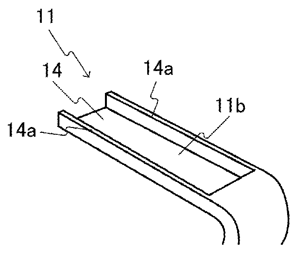
[0055]An angular plate 1 that is an implant in a first embodiment of the present invention will be described below with reference to FIGS. 1A, 1B, 1C, 2A, and 2B. The angular plate 1 is a device for fixing a bone fracture area, and includes a bone supporting plate part 10 and a blade part 11.
[0056]The bone supporting plate part 10 is formed in a substantially plate shape. One plane of the bone supporting plate part 10 in the thickness direction is an inner surface 10a of the bone supporting plate part 10. Another plane of the bone supporting plate part 10 in the thickness direction is an outer surface 10b of the bone supporting plate part 10. The inner surface 10a of the bone supporting plate part 10 is a surface to come into contact with the bone, as described below.
[0057]As shown in FIG. 1A, the bone supporting plate part 10 extends substantially linearly and curves toward the outer surface 10b side of the bone supporting plate part 10 ...
second embodiment
2. Second Embodiment
2-1. General Configuration
[0127]A plate for an epiphysis 2 that is an implant of a second embodiment of the present invention will be described below with reference to FIGS. 8 and 9. The plate for an epiphysis 2 is mainly used for an epiphysis, and has no blade that is provided to the angular plate 1. The plate for an epiphysis 2 includes a bone supporting plate part 20 and an edge plate part 21.
[0128]As shown in FIG. 8, the bone supporting plate part 20 is formed in a plate shape such as a band. The length of the bone supporting plate part 20 in the widthwise direction is substantially constant over its length. One plane of the bone supporting plate part 20 in the thickness direction (the rear side of the paper of the drawing) is an inner surface 20a of the bone supporting plate part 20. Another plane of the bone supporting plate part 20 in the thickness direction (the top side of the paper) is an outer surface 20b of the bone supporting plate part 20. The inner...
third embodiment
3. Third Embodiment
3-1. General Configuration
[0141]An intramedullary nail 3 that is an implant of a third embodiment of the present invention will be described below with reference to FIGS. 11 and 12. The intramedullary nail 3 is referred to as an ender nail. As shown in FIG. 11, the intramedullary nail 3 has a linear structure part 30 and a head part 31.
[0142]The linear structure part 30 is formed in a linear shape or a bar shape. For example, the shape of cross section of the linear structure part 30 may be a curved shape such as a circular shape or an elliptical shape or a polygon such as a tetragon or a pentagon, though the shape thereof is not particularly limited. As shown in FIG. 11, the linear structure part 30 is in an arched shape. However, the shape of the linear structure part 30 may be a shape in which the linear structure part 30 can be curved or bent into another shape using a predetermined device.
[0143]The head part 31 is a part that is one end of the linear structur...
PUM
 Abstract
Description
Claims
Application Information
 - Generate Ideas
- Intellectual Property
- Life Sciences
- Materials
- Tech Scout
- Unparalleled Data Quality
- Higher Quality Content
- 60% Fewer Hallucinations
Browse by: Latest US Patents, China's latest patents, Technical Efficacy Thesaurus, Application Domain, Technology Topic, Popular Technical Reports.
© 2025 PatSnap. All rights reserved.Legal|Privacy policy|Modern Slavery Act Transparency Statement|Sitemap|About US| Contact US: help@patsnap.com