Antireflection film, optical element, and optical system

a technology of anti-reflection film and optical element, applied in the field of anti-reflection film, optical element, optical system, can solve the problems of low mechanical strength of film, weak to external force such as wiping, parts such as outermost surfaces, front surfaces, etc., and achieve the effect of lowering the contrast of an image and high mechanical strength

Inactive Publication Date: 2018-04-05
FUJIFILM CORP
View PDF3 Cites 8 Cited by
  • Summary
  • Abstract
  • Description
  • Claims
  • Application Information

AI Technical Summary

Benefits of technology

[0046]Since all of the antireflection films according to the present invention have an uneven structure and a porous structure, the mechanical strength is high and the films can be applied to the surface of an optical member which is touched by a hand of a user. In addition, since the uneven structure and the porous structure have fluctuations

Problems solved by technology

However, since these films have a fine structure on the surface thereof, there are defects that the film has low mechanical strength and is very weak to an external force such as wiping.
Therefore, portions such as outermost

Method used


Image

  • Antireflection film, optical element, and optical system
  • Antireflection film, optical element, and optical system
  • Antireflection film, optical element, and optical system

Examples


examples

[0120]Hereinafter, Examples and Comparative Examples of the present invention will be described. The optimization of the film thickness and the simulation of the wavelength dependence of the reflectance were performed by using Essential Macleod (developed by Thin Film Center Inc.).

examples 1-1 and 1-2

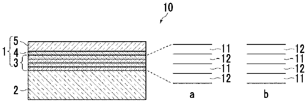
[0121]Layer configurations from a substrate to air as a medium were set as shown in Table 2.

[0122]The refractive index of the substrate was 1.61, the interlayer adopted a two-layer structure including a SiO2 layer having a refractive index of 1.46235 as a layer of low refractive index and a Nb2O5 layer having a refractive index of 2.3955 as a layer of high refractive index, the metal layer was formed of Ag, and the dielectric layer was formed of MgF2. Then, the optimization of the film thickness was performed so as to minimize the reflectance. In the following table, 1.61 in the substrate constitutional material column means a material having a refractive index of 1.61.

[0123]In Example 1-1, as the refractive index of Ag, the refractive index shown in “Optical constants of metals, in American Institute of Physics Handbook, McGraw Hill Book Company: New York and London. p. 6.124-6.156” (hereinafter, referred to as “Reference Document 2”) was used. On the other hand, in Example 1-2, as...

example 2

[0127]A layer configuration from a substrate to air as a medium was set as shown in Table 3.

[0128]S-NBH5 (manufactured by OHARA INC.) was used for the substrate, the interlayer adopted a two-layer structure including a SiO2 layer having a refractive index of 1.46235 as a layer of low refractive index and a Nb2O5 layer having a refractive index of 2.3955 as a layer of high refractive index, the metal layer was formed of Ag, and the dielectric layer was formed of MgF2. Then, the optimization of the film thickness was performed so as to minimize the reflectance.

TABLE 3Example 2ConstitutionalPhysical filmLayermaterialRefractive indexthickness (nm)MediumAir1—Dielectric layerMgF21.385787.28Metal layerAg0.054.62Interlayer 1Nb2O52.395515.52Interlayer 2SiO21.46235176.51SubstrateS-NBH 51.66393—

[0129]The simulation result of the reflectance of the antireflection film of Example 2 with respect to light incident at a light incidence angle of 0° (light vertically incident to the surface) is shown...


PUM

PropertyMeasurementUnit
Nanoscale particle sizeaaaaaaaaaa
Thicknessaaaaaaaaaa

Abstract

This antireflection film includes a dielectric layer having a surface exposed to air and having a refractive index of 1.35 or more and 1.51 or less, a metal layer having an interface with the dielectric layer, containing silver, and having a thickness of 5 nm or less, and an interlayer having an interface with the metal layer and constituted by a laminate formed by alternately laminating total four layers or more of a layer of high refractive index having a relatively high refractive index and a layer of low refractive index having a relatively low refractive index and is laminated on a substrate having a refractive index of 1.61 or more in the order of the interlayer, the metal layer, and the dielectric layer.

Description

CROSS REFERENCE TO RELATED APPLICATIONS[0001]The present application is a Continuation of PCT International Application No. PCT / JP2016 / 002488 filed on May 23, 2016, which claims priority under 35 U.S.C. § 119(a) to Japanese Patent Application No. 2015-108398 filed on May 28, 2015 and Japanese Patent Application No. 2015-168939 filed on Aug. 28, 2015. Each of the above applications is hereby expressly incorporated by reference, in its entirety, into the present application.BACKGROUND OF THE INVENTION1. Field of the Invention[0002]The present invention relates to an antireflection film, an optical element including an antireflection film, and an optical system including the optical element.2. Description of the Related Art[0003]In the related art, in a lens (transparent substrate) formed of a light transmitting member such as glass or a plastic, an antireflection film is provided on a light incident surface in order to reduce the loss of transmitted light caused by surface reflection....

Claims


Application Information

Patent Timeline
IPC IPC(8): G02B1/116B32B7/02B32B15/04G02B15/20G02B15/163
CPCG02B1/116B32B7/02B32B15/04G02B15/20G02B15/163B32B2307/418B32B2309/105B32B9/00G02B15/16G02B15/145
Inventor SONODA, SHINICHIROYASUDA, HIDEKIOHTSU, AKIHIKO
Owner FUJIFILM CORP
Why Eureka
Try Eureka