Semiconductor Material Doping

a technology of semiconductor materials and semiconductor materials, applied in the field of semiconductor device fabrication, can solve the problems of difficult control of doping during the manufacture of many types of devices fabricated with wide band gap semiconductor materials, and the conductivity of p-type algan is severely limited, and achieves the effect of facilitating a real space transfer of holes

Active Publication Date: 2018-04-19
SENSOR ELECTRONICS TECH
View PDF11 Cites 3 Cited by
  • Summary
  • Abstract
  • Description
  • Claims
  • Application Information

AI Technical Summary

Benefits of technology

[0011]A fourth aspect of the invention provides a method of fabricating a group III nitride semiconductor structure, the method comprising: designing a superlattice layer including a quantum well and an immediately adjacent barrier to facilitate a real space transfer of holes across the immediately adjacent barrier, wherein the designing includes: selecting a target valence band discontinuity between the quantum well and the immediately adjacent barrier such that a dopant energy level of a barrier dopant in the immediately adjacent barrier is at least one of: within three thermal energies of a valence energy band edge for the quantum well or substantially aligned with a ground state energy for free carriers in a valence energy band for the quantum well; and selecting a target thickness of each of the quantum well and the adjacent barrier based on a characteristic size of a wave function for the dopant in the immediately adjacent barrier, wherein the target thickness is less than the characteristic size; and forming the quantum well and the adjacent barrier in the structure using group III nitride materials having an actual valence band discontinuity corresponding to the target valence band discontinuity, and actual thicknesses equal to or less than the target thicknesses.
[0012]A fifth aspect of the invention provides a device comprising: a radiation generating structure; and a group III nitride superlattice layer located adjacent to the radiation generating structure, wherein the superlattice layer is at least partially transparent to radiation generated by the radiation generating structure, and wherein the superlattice layer comprises: a plurality of quantum wells; and a plurality of barriers alternating with the plurality of quantum wells, wherein a quantum well of the plurality of quantum wells and an immediately adjacent barrier of the plurality of barriers are formed of group III nitride materials having a valence band discontinuity such that a dopant energy level of a barrier dopant in the immediately adjacent barrier is at least one of: within three thermal energies of a valence energy band edge for the quantum well or substantially aligned with a ground state energy for free carriers in a valence energy band for the quantum well and thicknesses equal to or less than a characteristic size of a wave function for the dopant in the immediately adjacent barrier.
[0013]A sixth aspect of the invention provides a method of fabricating a deep ultraviolet light emitting device, the method comprising: forming a deep ultraviolet light generating structure; and forming a group III nitride superlattice layer located adjacent to the radiation generating structure, wherein the superlattice layer comprises: a plurality of quantum wells; and a plurality of barriers alternating with the plurality of quantum wells, wherein a quantum well of the plurality of quantum wells and an immediately adjacent barrier of the plurality of barriers are formed of group III nitride materials having a valence band discontinuity such that a dopant energy level of a barrier dopant in the immediately adjacent barrier is at least one of: within three thermal energies of a valence energy band edge for the quantum well or substantially aligned with a ground state energy for free carriers in a valence energy band for the quantum well and thicknesses equal to or less than a characteristic size of a wave function for the dopant in the immediately adjacent barrier.
[0014]The illustrative aspects of the invention are designed to solve one or more of the problems herein described and / or one or more other problems not discussed.

Problems solved by technology

Controlling doping during the manufacture of many types of devices fabricated with wide band gap semiconductor materials is difficult.
In particular, impurity levels for wide band gap semiconductor materials are deep and the activation of the impurities is inefficient, thereby making the doping more difficult to control.
As a result, the conductivity of p-type AlGaN is severely limited, which is extremely detrimental to the performance of deep ultraviolet light emitting diodes (LEDs).
However, as illustrated by FIG. 2, the conductance in a direction perpendicular to the two-dimensional hole gas is extremely small.

Method used


Image

  • Semiconductor Material Doping
  • Semiconductor Material Doping
  • Semiconductor Material Doping

Examples


Embodiment Construction

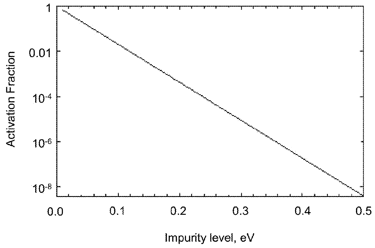
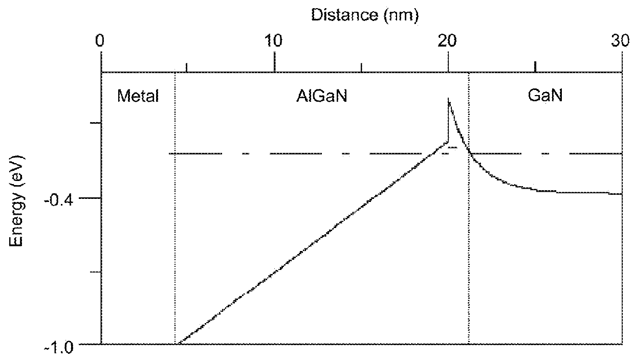
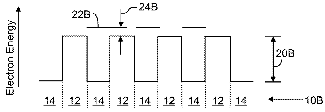
[0033]As indicated above, aspects of the invention provide a solution for designing and / or fabricating a structure including a quantum well and an adjacent barrier. A target band discontinuity between the quantum well and the adjacent barrier is selected to coincide with an activation energy of a dopant for the quantum well and / or barrier. For example, a target valence band discontinuity can be selected such that a dopant energy level of a dopant in the adjacent barrier coincides with a valence energy band edge for the quantum well and / or a ground state energy for free carriers in a valence energy band for the quantum well. Additionally, a target doping level for the quantum well and / or adjacent barrier can be selected to facilitate a real space transfer of holes across the barrier. The quantum well and the adjacent barrier can be formed such that the actual band discontinuity and / or actual doping level(s) correspond to the relevant target(s). The resulting structure can provide a l...


PUM


Abstract

A solution for designing and/or fabricating a structure including a quantum well and an adjacent barrier is provided. A target band discontinuity between the quantum well and the adjacent barrier is selected to coincide with an activation energy of a dopant for the quantum well and/or barrier. For example, a target valence band discontinuity can be selected such that a dopant energy level of a dopant in the adjacent barrier coincides with a valence energy band edge for the quantum well and/or a ground state energy for free carriers in a valence energy band for the quantum well. Additionally, a target doping level for the quantum well and/or adjacent barrier can be selected to facilitate a real space transfer of holes across the barrier. The quantum well and the adjacent barrier can be formed such that the actual band discontinuity and/or actual doping level(s) correspond to the relevant target(s).

Description

REFERENCE TO RELATED APPLICATIONS[0001]The current application is a continuation-in-part of U.S. Patent Application No. 15 / 495,169, filed on 24 Apr. 2017, which is a continuation of U.S. patent application Ser. No. 15 / 069,272, filed on 14 Mar. 2016, which is a continuation-in-part of U.S. Patent application Ser. No. 13 / 803,753, filed on 14 Mar. 2013, which claims the benefit of U.S. Provisional Application No. 61 / 610,658, filed on 14 Mar. 2012 and U.S. Provisional Application No. 61 / 768,833, filed on 25 Feb. 2013, and which is a continuation-in-part of U.S. patent application Ser. No. 13 / 162,908, filed on 17 Jun. 2011, which is a continuation-in-part of U.S. patent application Ser. No. 12 / 960,476, filed on 4 Dec. 2010, which claims the benefit of U.S. Provisional Application No. 61 / 266,523, filed on 4 Dec. 2009, all of which are hereby incorporated by reference. The government has certain rights in the invention.GOVERNMENT LICENSE RIGHTS[0002]This invention was made with government ...

Claims


Application Information

Patent Timeline
Patent Type & Authority Applications(United States)
IPC IPC(8): H01L33/06H01L33/32H01L33/00H01L29/15H01L29/20B82Y10/00B82Y20/00H01L29/201H01L29/207H01L33/04H01S5/20H01S5/32H01S5/34H01S5/343
CPCH01L33/04B82Y10/00H01L29/2003H01L29/201H01S5/2009H01S5/3211H01S5/3216H01S5/3407H01S5/34333H01L29/207B82Y20/00H01L29/15H01L33/06H01L33/32H01L33/0075H01L29/155
Inventor SHATALOV, MAXIM S.GASKA, REMIGIJUSYANG, JINWEISHUR, MICHAELDOBRINSKY, ALEXANDER
Owner SENSOR ELECTRONICS TECH
Why Eureka
Try Eureka