Ophthalmic laser delivery apparatus using MEMS micromirror arrays for scanning and focusing laser beam

a laser beam and laser beam technology, applied in laser surgery, eye surgery, instruments, etc., can solve the problems of large focal spot size, single flat mirror cannot correct wavefront aberration, and limit the scan pattern and speed that can be executed, so as to prevent large acceleration during laser scan execution and large inertia

Active Publication Date: 2018-04-26
AMO DEVMENT
View PDF9 Cites 6 Cited by
  • Summary
  • Abstract
  • Description
  • Claims
  • Application Information

AI Technical Summary

Benefits of technology

[0007]In conventional ophthalmic laser systems described above, in which the laser delivery system uses actuation of galvanometers-driven mirrors to scan the laser beam in the x and y directions, the galvo mirrors are relatively large and have relatively large inertia that may prevent large accelerations during execution of the laser scan. For example, the galvo mirror that executes the laser scan must decelerate before the scan trajectory switches direction. The larger the moments of inertia of the galvo mirrors, the longer such deceleration or acceleration requires. As a result, a particular galvo mirror system has an inherent maximum acceleration that limits the scan patterns and speed that can be executed with the galvo mirror system.

Problems solved by technology

As a result, a particular galvo mirror system has an inherent maximum acceleration that limits the scan patterns and speed that can be executed with the galvo mirror system.
A single flat mirror cannot correct wavefront aberrations that are invariably present in laser beams produced by the various optical components of the system.
Aberrations in the laser delivery system can result in undesirably large focal spot sizes (i.e., the laser beam cannot be precisely focused to a small focal spot).
This means delivering far more energy to the eye than strictly required, increasing unnecessarily the laser exposure to the patient.
Moreover, such energy requirement could in fact preclude certain procedures (for example, sideport incisions in some cases) because they would not be compliant with laser safety regulations.

Method used


Image

  • Ophthalmic laser delivery apparatus using MEMS micromirror arrays for scanning and focusing laser beam
  • Ophthalmic laser delivery apparatus using MEMS micromirror arrays for scanning and focusing laser beam
  • Ophthalmic laser delivery apparatus using MEMS micromirror arrays for scanning and focusing laser beam

Examples


first embodiment

[0032]In a first embodiment, the beam scanner 40 employs two micromirror arrays 41, to scan the laser beam in the x-direction and the y-direction, respectively. The two arrays may have identical structures. In each micromirror array 41, each micromirrors 42 only rotates around one axis, and therefore scans the laser beam in one direction. The two arrays 41 are disposed in series along the optical path, but oriented such that their rotation axes are perpendicular to each other. In this embodiment, all micromirrors 42 in the same array 41 are controlled to rotate synchronously in identical manners; thus, all micromirrors are parallel to each other during scanning. When the input laser beam is a collimated beam, the beam is reflected by the individual micromirrors 42 of the array 41 to form a collimated output beam; as such, the micromirror arrays 41 in this embodiment do not correct the optical aberration present in the laser beam. The output laser beam from the scanner 40 is focused ...

second embodiment

[0034]In a second embodiment, the beam scanner 40 employs a single micromirror array 41 in which each micromirror 42 has two independent orthogonal axes of rotation. The corresponding rotation axes of all micromirrors in the array are parallel to each other. Typically, a dual-axis micromirror has a fast axis and a slow axis. The micromirrors 42 are controlled to rotate around both axes to scan the laser beam in both the x-direction and the y-direction. In this embodiment, all micromirrors 42 in the array 41 are controlled to rotate synchronously in identical manners; thus, all micromirrors are parallel to each other during scanning. Thus, the micromirror array 41 reflects a collimated input laser beam to form a collimated output beam; as such, the micromirror array 41 in this embodiment does not correct the optical aberration present in the laser beam. The output laser beam from the scanner 40 is focused by the focusing optics 28 to a focal spot within the treatment area of the eye....

third embodiment

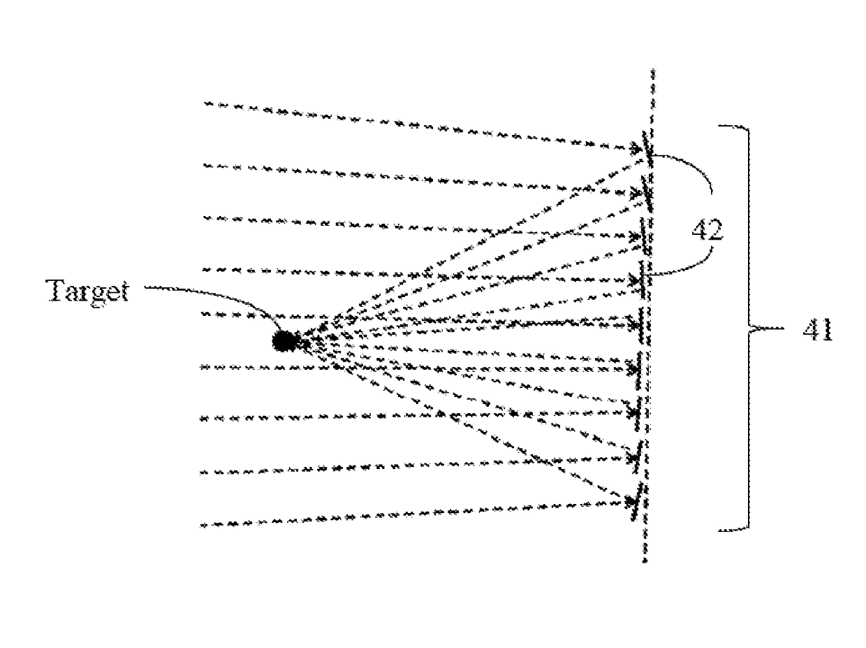
[0035]In a third embodiment, the beam scanner 40 employs a single micromirror array 41 in which each micromirror 42 has two axes of rotation. The individual micromirrors 42 in the array 41 are independently controlled to rotate to desired angles (around both axes) so as to correct the optical aberration in the laser beam.

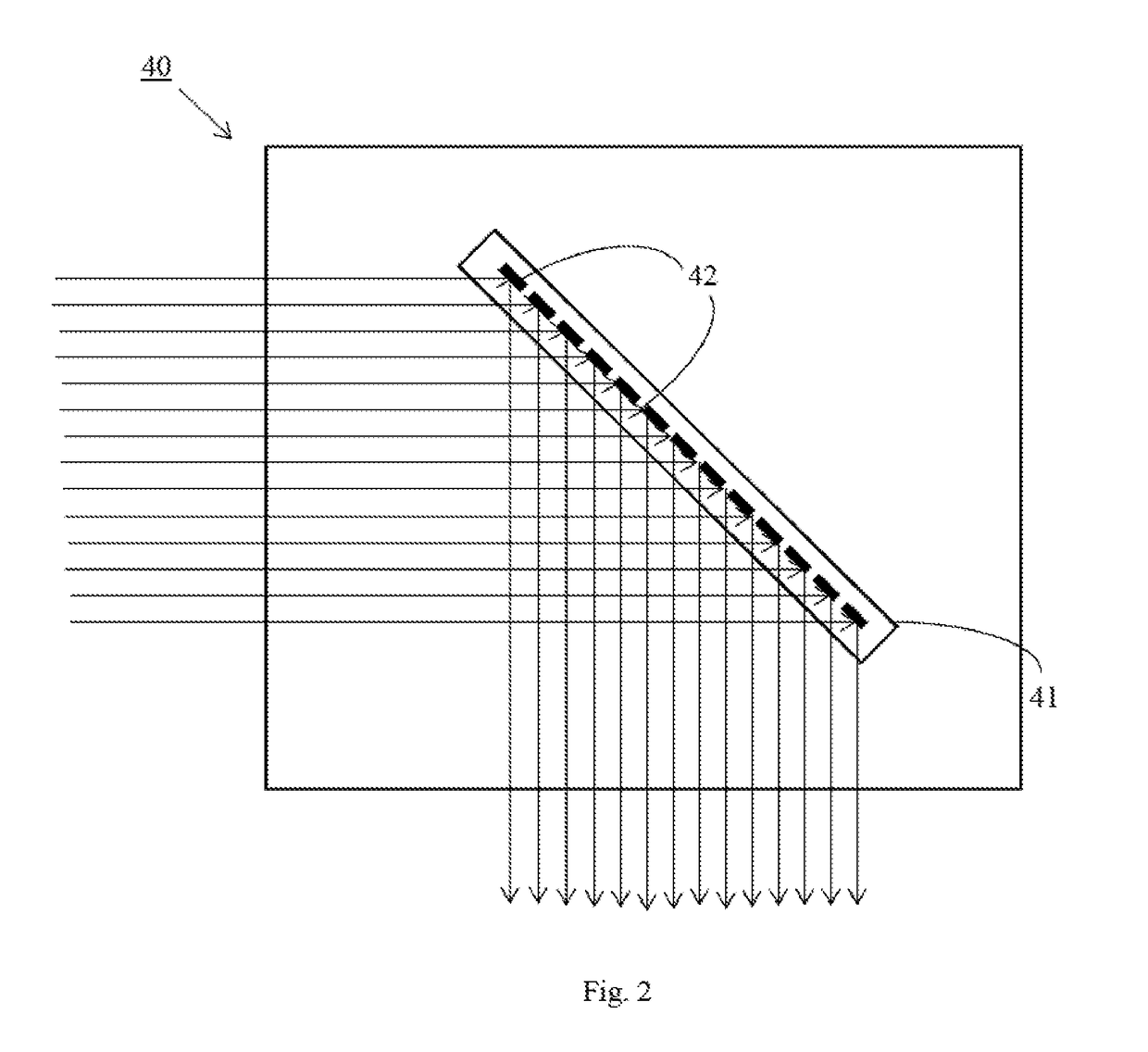
[0036]FIGS. 3 and 4 schematically illustrate the effect of aberration correction by a micromirror array. FIG. 3 schematically illustrates a conventional galvo mirror; it schematically depicts a converging input light beam onto a single flat galvo mirror, and the converging beam, after reflection by the flat mirror, forms a focal spot of a relatively large size, due to the optical aberration present in the input light beam caused by of upstream optical elements. FIG. 4 schematically illustrates the same input light beam as reflected by a micromirror array 41, in which individual micromirrors 42 are independently controlled to desired angles around both rotation axes,...


PUM


Abstract

In a laser delivery system for an ophthalmic laser surgery system, a laser beam scanner employs a single or two MEMS micromirror arrays. Each micromirror in the array is capable of being independently actuated to rotate to desired angles. In one embodiment, one or two micromirror arrays are controlled to scan a laser beam in two directions. In another embodiment, a micromirror array is controlled to both correct optical aberrations in the laser beam and scan the laser beam in two directions. In yet another embodiment, a micromirror array is controlled to cause the laser beam to be focused to multiple focal spots simultaneously and to scan the multiple focal spot simultaneously. The ophthalmic laser surgery system also includes an ultrashort pulse laser, a laser energy control module, focusing optics and other optics, and a controller for controlling the laser beam scanner and other components of the system.

Description

RELATED APPLICATIONS[0001]This application claims priority to, and the benefit of, under U.S.C. § 119(e) of U.S. Provisional Appl. No. 62 / 413,370, filed on Oct. 26, 2016, which is incorporated herein by reference in its entirety.BACKGROUND OF THE INVENTIONField of the Invention[0002]This invention relates to a laser delivery system for ophthalmic procedures, and in particular, it relates to such a laser delivery system that employs MEMS micromirror arrays for scanning and focusing the laser beam.Description of Related Art[0003]Ophthalmic laser surgery systems use a laser delivery system to deliver a laser beam generated by a laser into a patient's eye. The laser delivery system focuses the laser beam and scans the focal spot over an area or volume of the eye (referred to as the treatment area or region) to achieve desired therapeutic effects, such as photoalteration of the eye tissues. FIG. 1 is a block diagram that schematically illustrates an ophthalmic laser surgery system 10. Th...

Claims


Application Information

Patent Timeline
Patent Type & Authority Applications(United States)
IPC IPC(8): A61F9/008G02B27/22
CPCA61F9/00804A61F9/00817G02B27/2271G02B27/285A61F2009/00897A61F2009/00872G02B27/18A61F9/008G02B26/0833G02B26/101G02B30/50
Inventor GONZALEZ, JAVIER G.
Owner AMO DEVMENT
Why Eureka
Try Eureka