Low cost and compact optical phased array with electro-optic beam steering

a phased array, electro-optic technology, applied in non-linear optics, wave based measurement systems, instruments, etc., can solve the problems of lithium niobate waveguides not being the best approach in volume manufacturing and overall cost, and design has a practical limitation in steering angl

Inactive Publication Date: 2018-05-03
QUANERGY SYST
View PDF5 Cites 26 Cited by
  • Summary
  • Abstract
  • Description
  • Claims
  • Application Information

AI Technical Summary

Problems solved by technology

This design has a practical limitation in terms of steering angle because of the channel spacing at the array of output waveguides.
Also, lithium niobate waveguides may not be the best approach in terms of volume manufacturing and overall cost.
However, these techniques use heaters to create relative phase differences among the array of waveguides.
Thus, this technique requires thermal management.
In addition, overall power consumption may be difficult in automotive applications.

Method used


Image

  • Low cost and compact optical phased array with electro-optic beam steering
  • Low cost and compact optical phased array with electro-optic beam steering
  • Low cost and compact optical phased array with electro-optic beam steering

Examples


Embodiment Construction

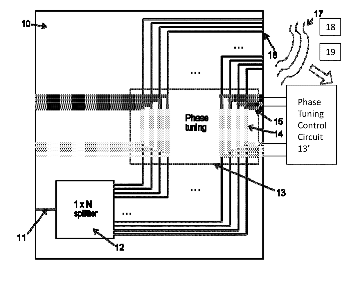
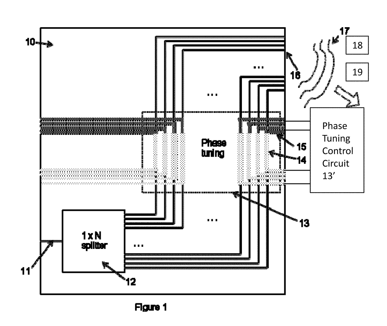
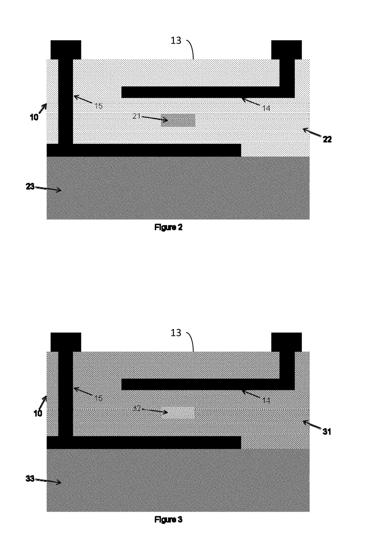
[0012]The schematic diagram of FIG. 1 depicts the top view of an optical phased array. It is based on a substrate 10 with a waveguide input 11 where light from an external source is coupled. Alternately, an integrated light source may be used to generate the light. The light is split by one or more optical power splitters 12 to form split signals. An array of waveguides receives the split signals. The array of waveguides includes a phase tuning region 13 which includes electrodes 14 and 15. The electrodes 14 and 15 induce an electro-optic effect in said array of waveguides in said phase tuning region 13 based upon a phase tuning control circuit 13′.

[0013]At the phase tuning region 13, the waveguide spacing is selected so that device elements such as electrodes and trenches can be fabricated within the region. Also, a large waveguide spacing, such as>10 μm, is designed for minimizing the electrically related crosstalk within the array of waveguides. Thus, the waveguide spacing in the...


PUM


Abstract

An apparatus has an input waveguide to receive light. An optical power splitter is connected to the input waveguide to form split signals. An array of waveguides receives the split signals. A phase tuning region includes electrodes within a cladding structure surrounding cores of the array of waveguides. The phase tuning region produces an electro-optic effect under the control of a phase tuning control circuit applying an electric field to the electrodes to render phase difference split signals within the array of waveguides. Output array waveguides emit the phase difference split signals as steered beams based on relative phase differences among the phase difference split signals.

Description

FIELD OF THE INVENTION[0001]The present invention relates to the field of spatial sensing using Time of Flight (ToF) LIDAR sensors. More particularly, the invention is a low cost and compact optical phased array ToF LIDAR sensor with electro-optic beam steering.BACKGROUND OF THE INVENTION[0002]Optical phased arrays (OPAs) have been studied for manipulating a small optical beam (e.g., a laser beam). OPAs represent an evolution of well-developed radio frequency (RF) counterparts, namely Phased Array Radar. Several groups studied optical phased arrays based on various technologies, such as liquid crystal (LC), microelectromechanical systems (MEMS) and optical waveguide devices.[0003]One application of OPAs is a Light Detection and Ranging (LIDAR) sensor for automotive systems. For example, a LIDAR sensor positioned on a vehicle collects information on objects around it while in motion. The collected information characterizes objects and live events around the vehicle. It is desirable t...

Claims


Application Information

Patent Timeline
Patent Type & Authority Applications(United States)
IPC IPC(8): G01S7/481G01S7/486G01S7/4865
CPCG01S7/4818G01S7/4865G01S7/4817G01S7/4814G02F1/2955
Inventor FUJITA, JUNICHIROELDADA, LOUAY
Owner QUANERGY SYST
Why Eureka
Try Eureka