Method and system for large field of view display with scanning reflector

a technology of scanning reflector which is applied in the field of large field of view display with scanning reflector, can solve the problems of large device size and limited field of view of conventional scanning image display in wearable devices for virtual reality or augmented reality applications, and achieve the effects of small device form factor, large device size and large field of view

Active Publication Date: 2018-05-03
MAGIC LEAP INC
View PDF3 Cites 95 Cited by
  • Summary
  • Abstract
  • Description
  • Claims
  • Application Information

AI Technical Summary

Problems solved by technology

Conventional scanning image displays in a wearable device for virtual reality or augmented reality applications often have limited field of view, because the scanning mirror has limited range of scan motion and design constraints in the arrangement of optical elements.
However, this arrangement can lead to a larger device size, which can be undesirable.

Method used


Image

  • Method and system for large field of view display with scanning reflector
  • Method and system for large field of view display with scanning reflector
  • Method and system for large field of view display with scanning reflector

Examples


Embodiment Construction

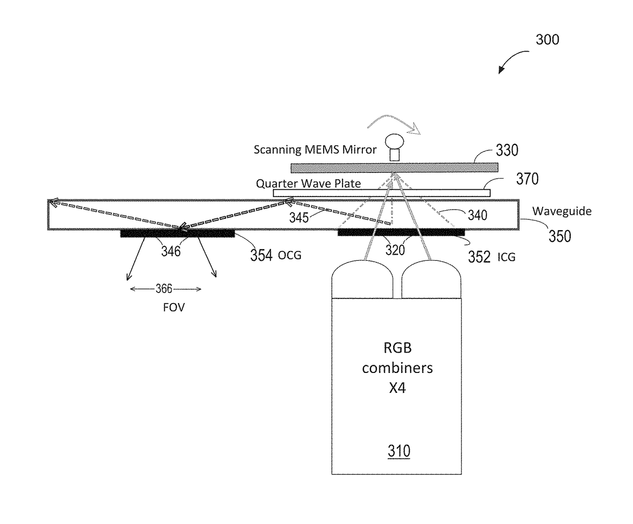
[0058]Embodiments of the present invention are directed to image display systems and methods for a wearable device that can provide a larger field of view (FOV) than conventional display systems.

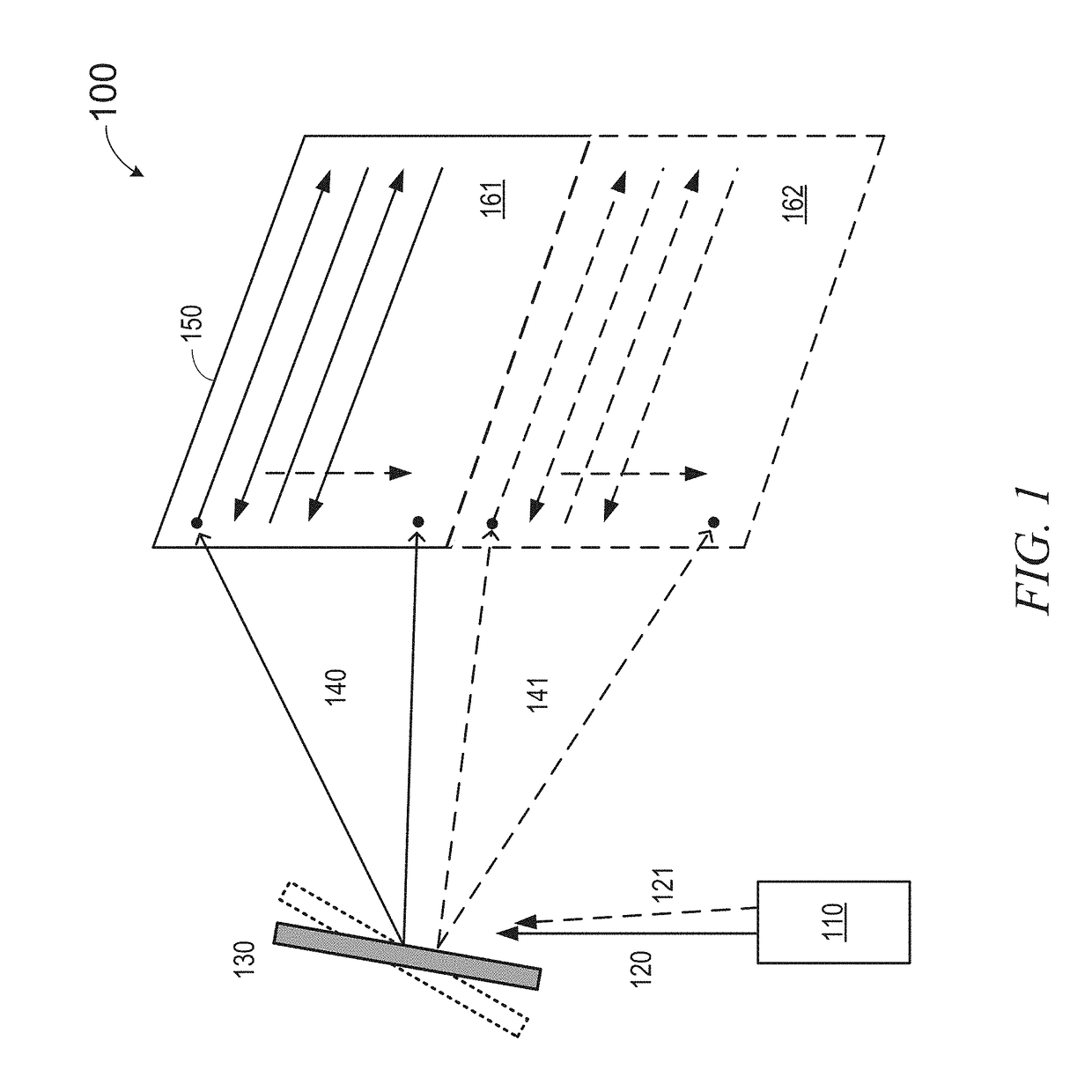
[0059]FIG. 1 is a simplified schematic diagram illustrating an image display system according to some embodiments of the present invention. In this example, the image display system 100 is a scanning display system including a scanning mirror that projects an image. Image display system 100 can be part of an eyepiece, e. g., a waveguide based eyepiece, in a wearable device. As shown in FIG. 1, image display system 100 includes a light source 110 and a scanning mirror 130 configured to form a raster scan image. Light source 110 can emit light that is imagewise modulated based on image data to form imagewise modulated light. Light source 110 is configured to emit light beams, e.g., beam 120, toward scanning mirror 130, which is configured to scan the reflected light 140 across a surface 150 to...


PUM


Abstract

An image display system includes an optical subsystem configured to emit a first light beam and a second light beam, wherein the first light beam illuminates a first portion of a composite field of view and the second beam illuminates a second portion of the composite field of view. A scanning mirror is positioned to intercept and reflect the first light beam and the second light beam. The system also has a waveguide with at least one input coupling optical element for receiving the first light beam and the second light beam into the waveguide. The waveguide also has an output coupling optical element for projecting a plurality of output light beams derived from the first light beam and the second light beam from the waveguide to illuminate the composite field of view.

Description

CROSS-REFERENCES TO RELATED APPLICATIONS[0001]This Application claims priority to U.S. Provisional Patent Application No. 62 / 414,484, filed on Oct. 28, 2016, U.S. Provisional Patent Application No. 62 / 532,968, filed on Jul. 14, 2017, and U.S. Provisional Patent Application No. 62 / 545,243, filed on Aug. 14, 2017, the contents of all of which are hereby incorporated by reference in their entirety for all purposes.BACKGROUND OF THE INVENTION[0002]Modern computing and display technologies have facilitated the development of systems for so-called “virtual reality” or “augmented reality” experiences, wherein digitally produced images or portions thereof are presented in a wearable device to a user in a manner wherein they seem to be, or may be perceived as, real. A virtual reality, or “VR,” scenario typically involves presentation of digital or virtual image information without transparency to other actual real-world visual input; an augmented reality, or “AR,” scenario typically involves...

Claims


Application Information

Patent Timeline
Patent Type & Authority Applications(United States)
IPC IPC(8): G02B26/12G02B26/10G02B27/10G02B5/18G02B5/30
CPCG02B26/123G02B26/129G02B26/103G02B27/1026G02B5/1842G02B5/3083G02B27/286G02B2027/0123G02B27/0172G02B5/18G02B26/0833G02B26/105G02B6/0016G02B6/0038G02B6/0011
Inventor YEOH, IVAN LI-CHUENEDWIN, LIONEL ERNESTFREEDMAN, BARAKMATHUR, VAIBHAVZHANG, XIAOYANGDALRYMPLE, TIMOTHY MARKCARLISLE, CLINTONOH, CHULWOOPREMYSLER, PHILIP
Owner MAGIC LEAP INC
Why Eureka
Try Eureka