
Light communications receiver and decoder with time to digital converters

a technology of light communication receiver and decoder, which is applied in the field of near infrared and visible light communication systems, can solve the problems of degrading the time of flight sensor measurement, adding photon shot noise, and extracting the required information, and achieves the effect of increasing the bandwidth

Active Publication Date: 2018-05-03
STMICROELECTRONICS (RES & DEV) LTD
View PDF8 Cites 26 Cited by
  • Summary
  • Abstract
  • Description
  • Claims
  • Application Information

AI Technical Summary

Benefits of technology

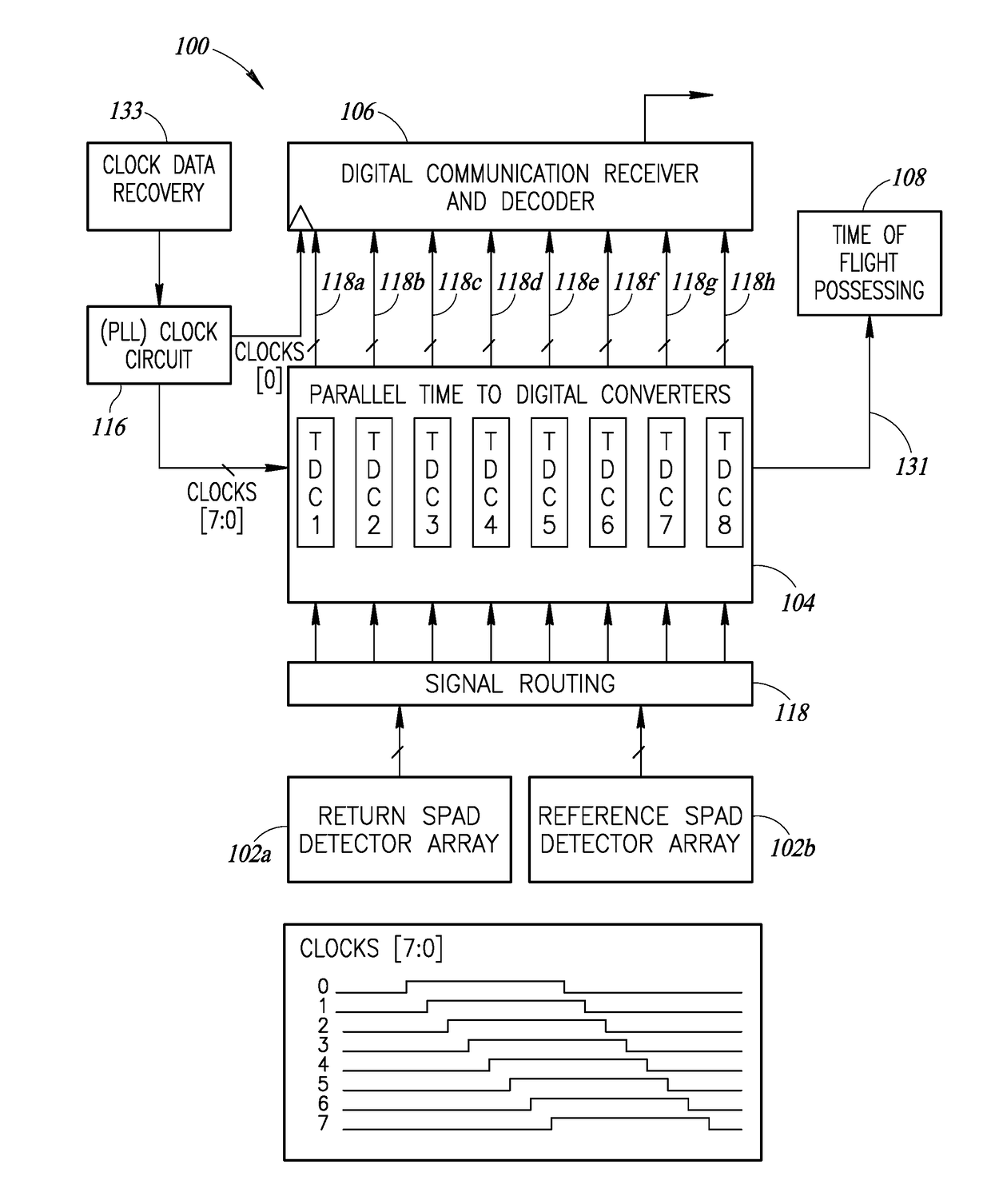
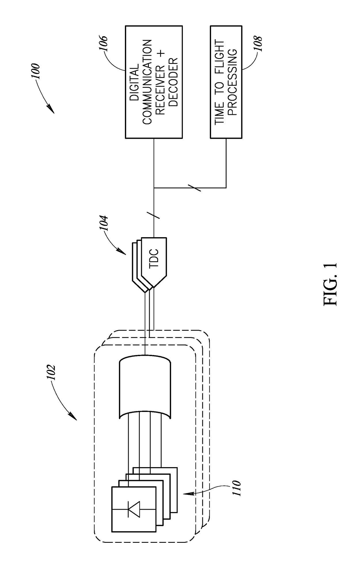
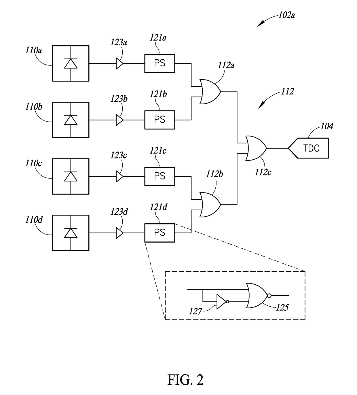
The present patent describes a system that can increase the bandwidth of a reflected emitted signal by using a light communication receiver and decoder with low signal intensity. It uses time to digital converters to synchronize the outputs from the light sensor and process the digital code stream to extract data from the received signal. The system can detect changes in the ambient light and remove it to output a decoded received data stream that corresponds closely to the reflected light. This is useful, for example, in a mobile device where the distance to an object being detected is not changing. The system uses a plurality of single photon avalanche diodes (SPAD array) and parallel time to digital converters to synchronize the output signals and determine flexible thresholds to compare with the current data. The technical effects of this system include increased bandwidth, improved data synchronization, and accurate detection of changes in the ambient light.

Problems solved by technology

It can be the case that the returned signal from a distant, low reflectance, target can be very low bringing challenges in extracting the required information.
This ambient light adds Photon Shot noise and degrades the time of flight sensor's measurement.
This noise contribution brings challenges in extracting the key parameters of the returned signal such as amplitude, time or phase shift, pulse time length (temporal width), etc.

Method used


Image

  • Light communications receiver and decoder with time to digital converters
  • Light communications receiver and decoder with time to digital converters
  • Light communications receiver and decoder with time to digital converters

Examples


Embodiment Construction

[0018]In the following description, certain specific details are set forth in order to provide a thorough understanding of various embodiments of the disclosure. However, one skilled in the art will understand that the disclosure may be practiced without these specific details. In other instances, well-known structures associated with electronic components and fabrication techniques have not been described in detail to avoid unnecessarily obscuring the descriptions of the embodiments of the present disclosure.

[0019]Unless the context requires otherwise, throughout the specification and claims that follow, the word “comprise” and variations thereof, such as “comprises” and “comprising,” are to be construed in an open, inclusive sense, that is, as “including, but not limited to.”

[0020]Reference throughout this specification to “one embodiment” or “an embodiment” means that a particular feature, structure or characteristic described in connection with the embodiment is included in at l...


PUM


Abstract

The present disclosure includes a method that includes generating a decoded output signal that corresponds to reflected light received by a plurality of single photon avalanche diodes (SPAD) by removing ambient light from a plurality of SPAD array output signals. The removing of ambient light including synchronizing the plurality of SPAD array output signals by using a plurality of parallel time to digital converters, each time to digital converter outputting a synchronized SPAD array output signal, determining a plurality of flexible thresholds for each one of the synchronized SPAD array output signals, comparing current data on the synchronized SPAD array output signals with the respective ones of the flexible threshold in a filter, and outputting the first output signal.

Description

BACKGROUNDTechnical Field[0001]The present disclosure is directed to near infrared and visible light communications systems that include time to digital converters.Description of the Related Art[0002]Time of flight sensors are incorporated in a variety of products for range finding, depth profiling, 3D imaging, and medical imaging, to name a few. Time of flight measurements include measuring a length of time between an emitted signal and a received signal. A distance can be calculated based on this length of time. Single Photo Avalanche Diode (SPAD) arrays are incorporated in time of flight sensors, where there is often a reference array and a return detection array. Each of the SPAD arrays receives the emitted signal.[0003]In order to measure the time light takes to travel a short distance in millimeter or centimeter range, very precise timing resolution is required. One method for achieving the required degree of timing accuracy is to employ SPAD devices and implement a Time to Di...

Claims


Application Information

Patent Timeline
Patent Type & Authority Applications(United States)
IPC IPC(8): H03M7/30G01J1/44G04F10/00G01S7/4861G01S7/4863G01S7/4865G01S17/10
CPCH03M7/30G01J2001/4466G04F10/005G01J1/44H03M7/14G01S7/4865G01S7/4873G01S17/10G01S7/4863G01S7/4861
Inventor DUTTON, NEALEMOORE, JOHN KEVIN
Owner STMICROELECTRONICS (RES & DEV) LTD
Learn More