System and method for automatically navigating a charted contour

a technology of automatic navigation and contour, applied in the field of marine navigation system and method, can solve the problems of inability to accurately apply, disadvantages of conventional navigation system, and rapid obsoleteness of paper charts, and achieve the effect of convenient application

Active Publication Date: 2018-05-10
JOHNSON OUTDOORS
View PDF4 Cites 5 Cited by
  • Summary
  • Abstract
  • Description
  • Claims
  • Application Information

AI Technical Summary

Benefits of technology

[0016]In a specific embodiment, the present method and system overcomes one or more of the limitations described above by providing for a rapid, easily applied automatic way of creating a navigable route from complex depth contour line or underwater feature contour line in a language understandable by and for transmission to various vessel control devices, which are configured to navigate the vessel.

Problems solved by technology

Because waterways and the underwater features of these waterways change, and because the methods of creating the cartography is becoming more exact, paper charts are quickly becoming obsolete.
Unfortunately, disadvantages exist with conventional navigation systems.
As an example, one disadvantage is that it is cumbersome and, depending on the detail provided by the underlying chart, may not be truly accurate.
Additionally, a certain amount of time is generally required to create the turn points necessary to generate a desired route, making it difficult to generate such a route while the vessel is underway.
In conventional navigation systems, the charts, codes, programs and systems typically have limited resources available for processing and converting complex chart and depth contour information.
For example, a fishing vessel may be in the vicinity of a desirable underwater feature, or at a desirable depth for fishing, but will typically traverse among various features and depths due to an inability of the navigation system to keep the vessel on a course in which the vessel's position tracks along the aforementioned desirable features or depths.

Method used


Image

  • System and method for automatically navigating a charted contour
  • System and method for automatically navigating a charted contour
  • System and method for automatically navigating a charted contour

Examples


Embodiment Construction

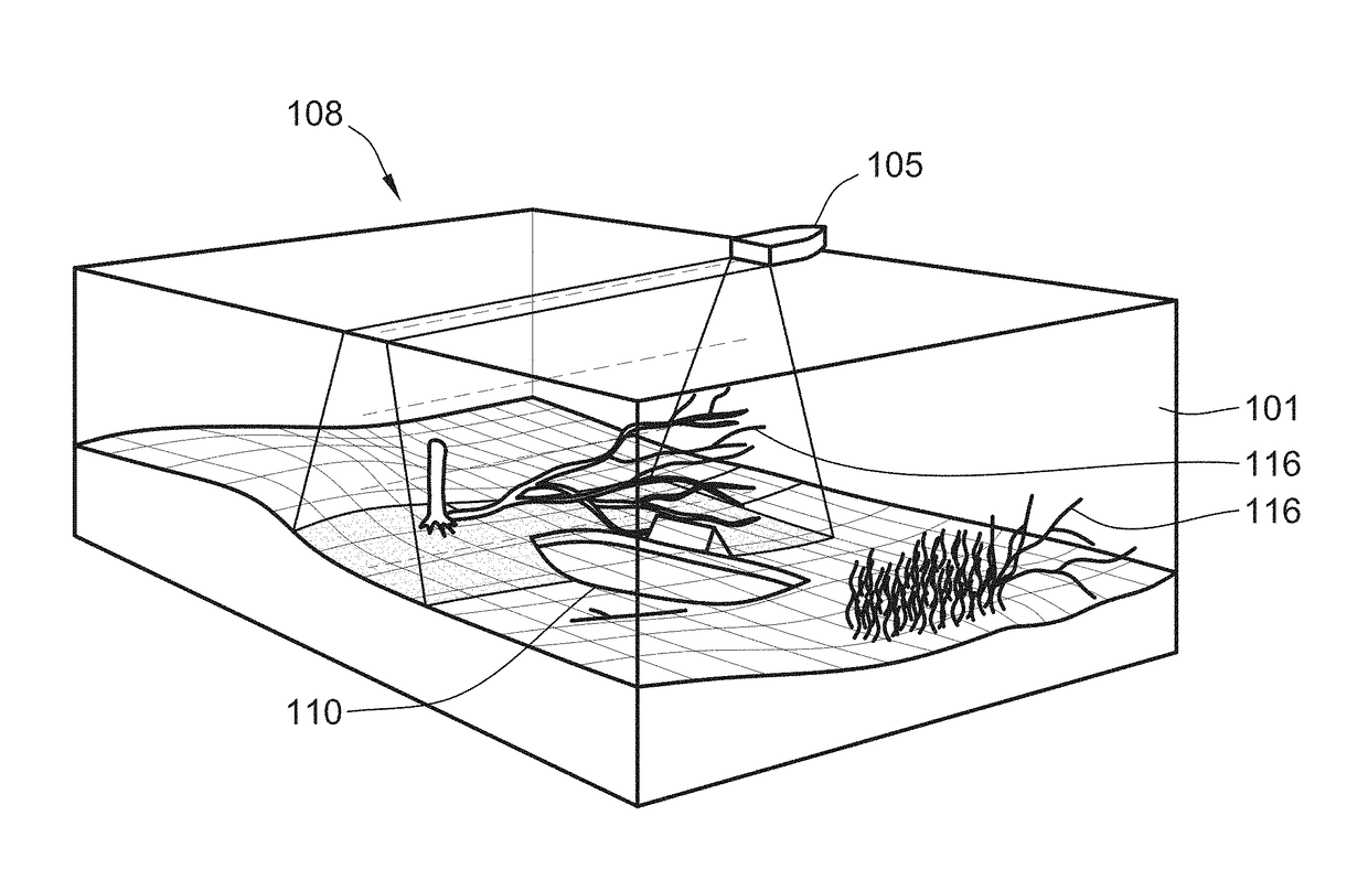
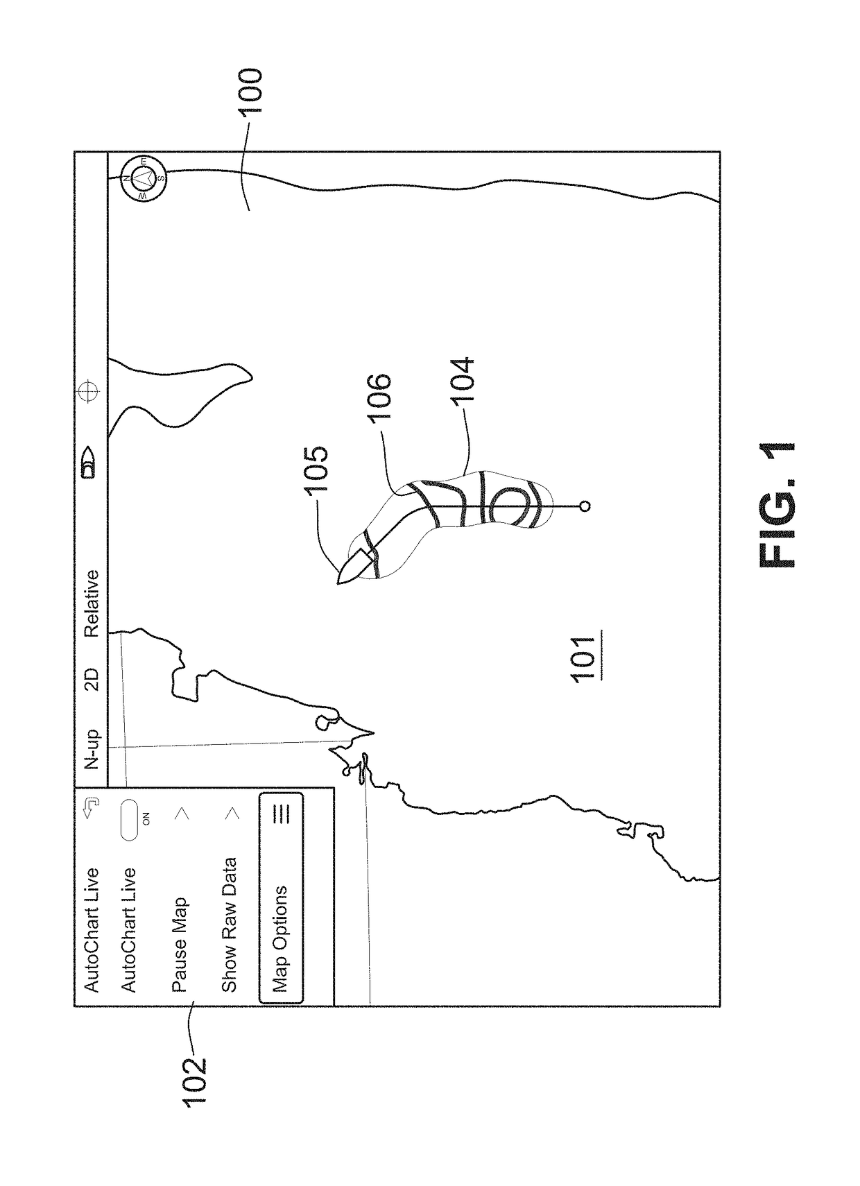
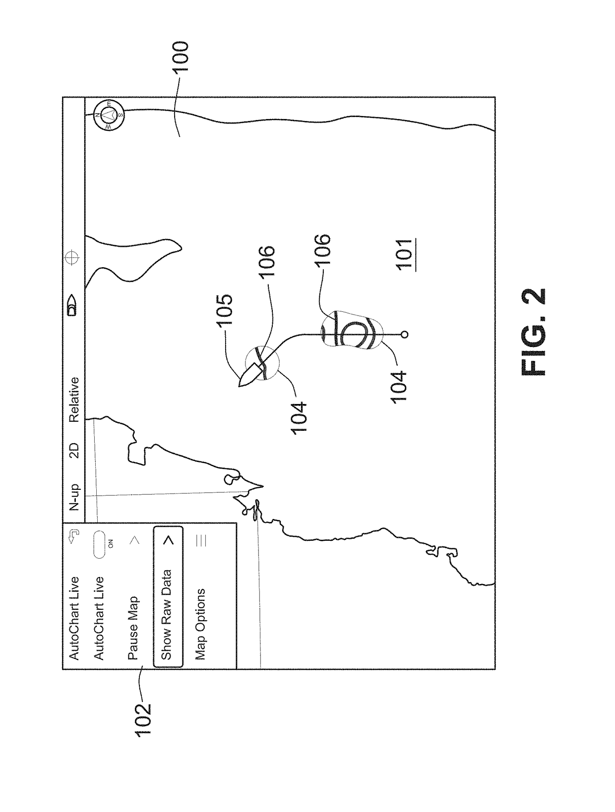
[0045]FIG. 1 shows an exemplary illustration of a chart 100 showing a boat 105 location on a chart 100 displayed for the user. The display may be that of a sonar imaging fish finder, for example. The chart 100 may be one that is stored in the fish finder memory, or as explained below, one that is generated via an automatic mapping function initiated using a sonar mapping system 200 (shown in FIG. 4). In a particular embodiment, the sonar mapping system 200 is configured to access the chart 100 in memory (not shown). Thus, the user may access, in memory, a desired chart for a body of water 101, for example the body of water on which the user is navigating. When the automatic charting function is operating, a control processor 208 (shown in FIG. 4) is configured to update the chart 100 with topographical data 104 in real time based on sonar data provided by a sonar transducer assembly, which could be mounted on the hull of the boat 105 such that the sonar beam from the transducer asse...


PUM


Abstract

A system for controlling a marine vessel has a sonar depth finder which displays a chart, stored in memory, for a body of water. The chart includes an underwater feature contour that defines a boundary of an underwater feature. The sonar depth finder includes a processor to create or update the topographical chart based on sonar data from a sonar transducer assembly. The sonar data includes information on the underwater feature. The processor can display and store the topographical chart. The user may select from the underwater feature contours on the depth finder display. The depth finder can generate a route for the marine vessel that includes a path along the selected underwater feature contours. A vessel control device, in communication with the depth finder, may receive transmissions, from the depth finder, which include the generated route. The vessel control device can automatically direct the marine vessel along the route.

Description

CROSS-REFERENCE TO RELATED PATENT APPLICATIONS[0001]This patent application claims the benefit of U.S. Provisional Patent Application No. 62 / 419,839, filed Nov. 9, 2016, and U.S. Provisional Patent Application No. 62 / 420,871, filed Nov. 11, 2016, the entire teachings and disclosure of which are incorporated herein by reference thereto.FIELD OF THE INVENTION[0002]This invention generally relates to a system and method for marine navigation.BACKGROUND OF THE INVENTION[0003]Sonar transducer assemblies are sometimes mounted on the hulls of watercrafts for various purposes, fish finding for example. U.S. Patent Publication No. 2013 / 0215719, published on Aug. 22, 2013, discloses a system including a sonar transducer assembly, deployed below the bottom of a boat hull, which provides 360-degree sonar imaging, the entire teachings and disclosure of which is incorporated herein by reference thereto. U.S. Patent Publication No. 2014 / 0269164, published Sep. 18, 2014, discloses a system includin...

Claims


Application Information

Patent Timeline
Patent Type & Authority Applications(United States)
IPC IPC(8): G05D1/02G01C21/20B63J99/00B63H20/00G01S15/89G01S7/62
CPCG05D1/0206G01C21/203B63J99/00B63H20/007G01S15/8902G01S7/6263B63J2099/006B63B2201/18B63B2213/02G01C13/008B63B49/00
Inventor PELIN, PERSALMON, PAUL D.
Owner JOHNSON OUTDOORS
Why Eureka
Try Eureka