Inductor and method for manufacturing the same

a manufacturing method and technology of an inductance, applied in the field of inductance, can solve the problems that the heating treatment requirement at a heating temperature above 600° c. cannot be satisfied, and achieve the effect of reducing direct current resistance and great inductan

Inactive Publication Date: 2018-05-10
SHENZHEN SUNLORD ELECTRONICS
View PDF0 Cites 0 Cited by
  • Summary
  • Abstract
  • Description
  • Claims
  • Application Information

AI Technical Summary

Benefits of technology

[0022]According to the present application, the conducting wire embedded in the magnetic body material can withstand heating treatment at a heating temperature of above 600° C., so that the magnetic conductivity of the magnetic body material that has been subject to heating treatment at a heating temperature of above 600° C. is higher. Therefore, when a length of a conducting wire is specified, an inductor having a greater inductance can be manufactured. Alternatively, when an inductance is specified, only a shorter conducting wire is needed, so that an inductor having a lower direct current resistance can be manufactured.

Problems solved by technology

Consequently, a requirement for the heating treatment at a heating temperature of above 600° C. cannot be satisfied.

Method used


Image

  • Inductor and method for manufacturing the same
  • Inductor and method for manufacturing the same
  • Inductor and method for manufacturing the same

Examples


Embodiment Construction

[0028]The following further describes exemplary embodiments of the present application in detail.

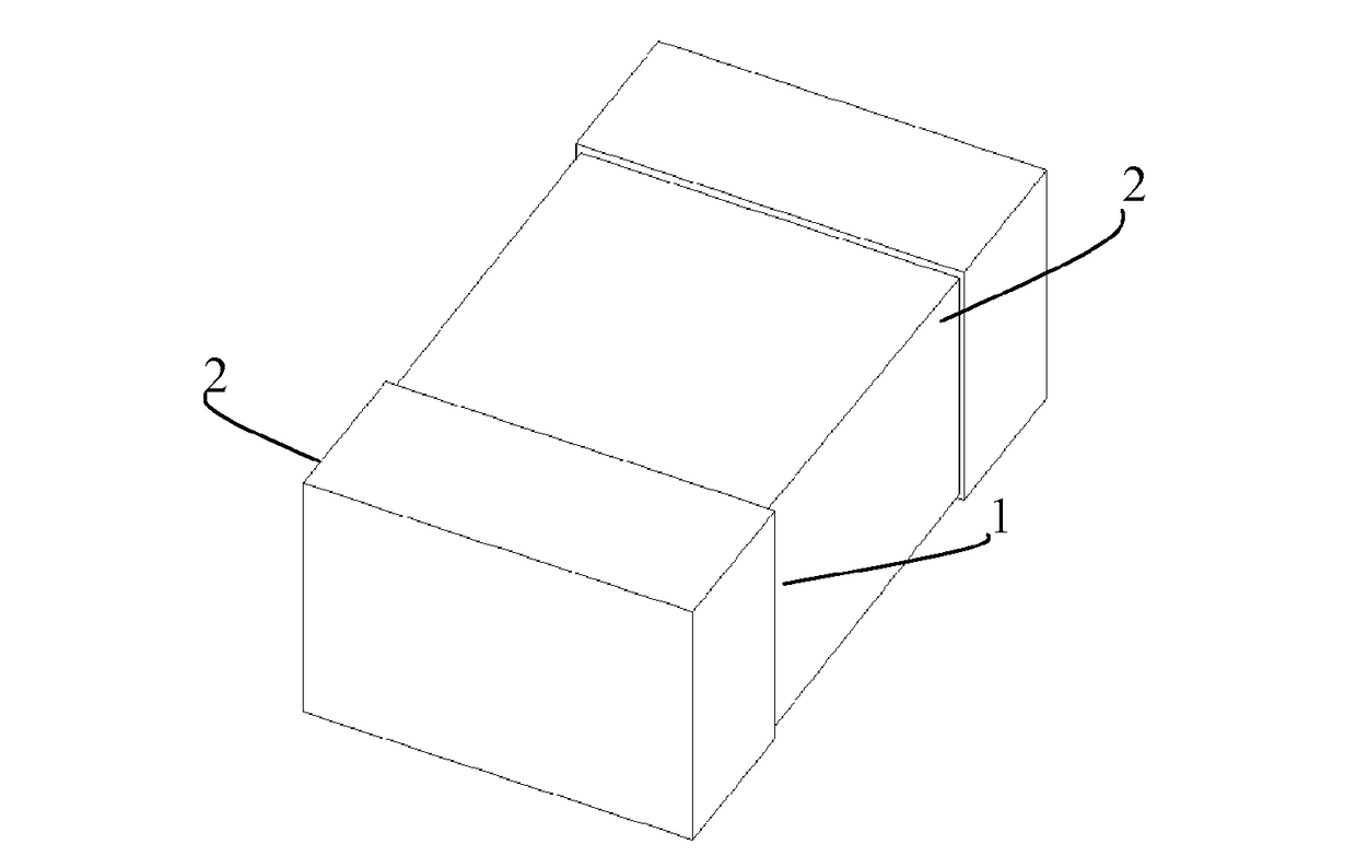
[0029]As shown in FIG. 1 to FIG. 4, in an embodiment, a method for manufacturing an inductor includes the following steps:

[0030]S1. Mix an organic adhesive and an inorganic insulation material to obtain a mixture.

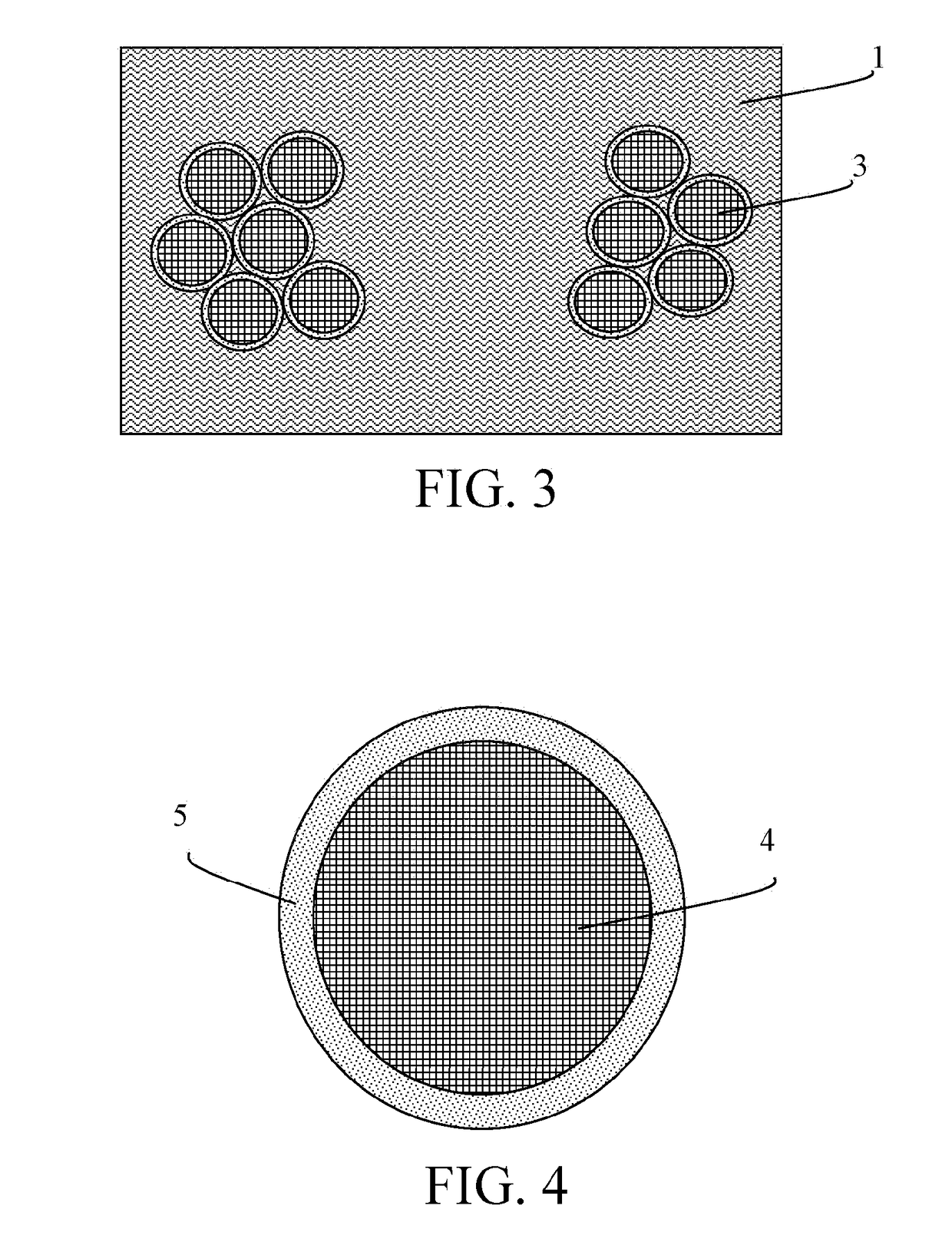
[0031]The organic adhesive maybe a resin adhesive, and the inorganic insulation material may be ceramic, glass, or a mixture of ceramic and glass. In the mixture, an inorganic insulation material 5 is dispersed in the resin adhesive.

[0032]S2. Coat the mixture on a surface of a conducting wire.

[0033]A material of a conducting wire 4 maybe a material having good conductivity, such as copper, nickel, silver, or gold. The inorganic insulation material is adhered to the conducting wire 4 by using an organic adhesive.

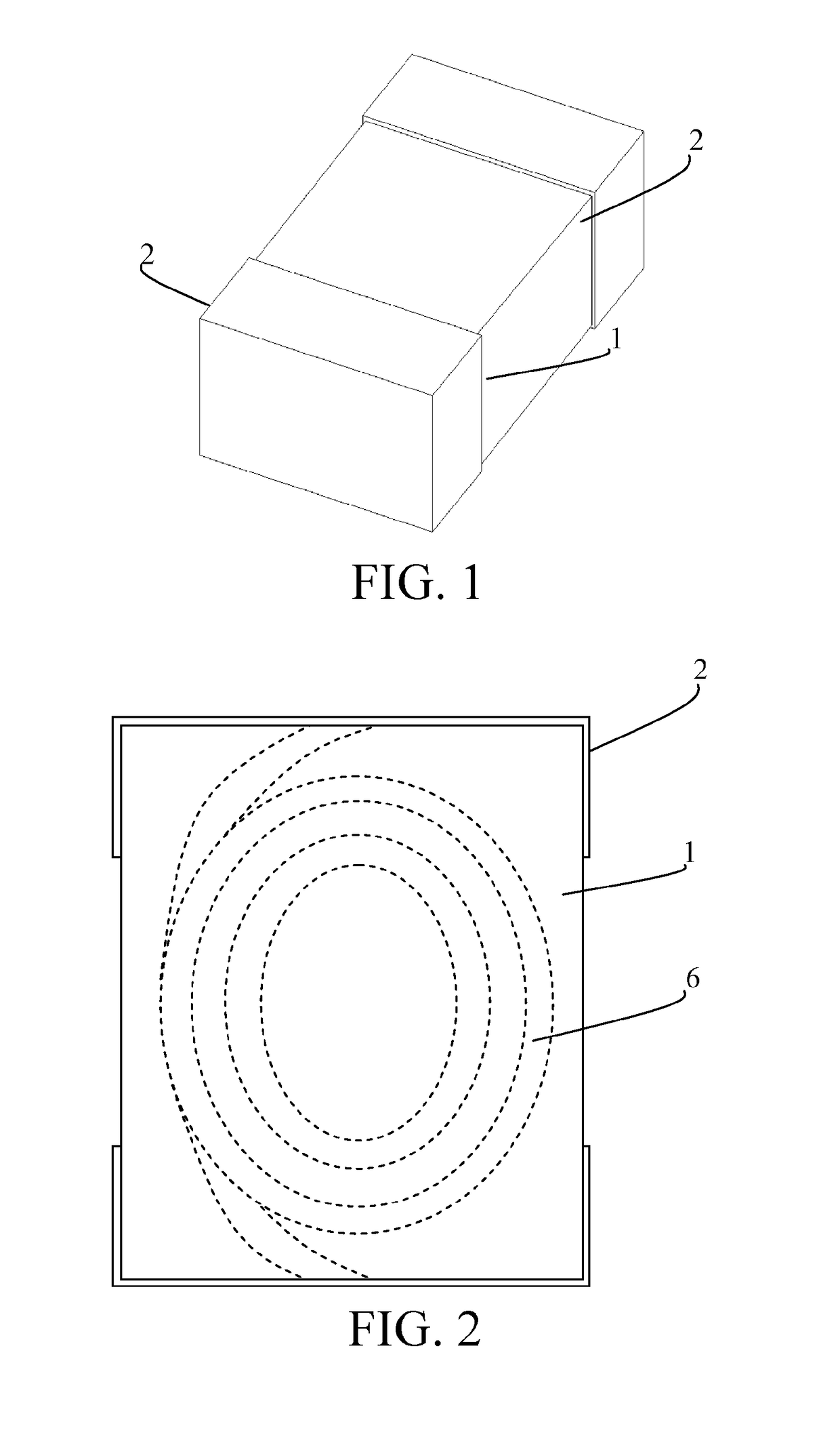
[0034]S3. Wind the conducting wire with the mixture on the surface to obtain a coil.

[0035]As shown in FIG. 2, the conducting wire 4 is wound by using a winding device, to...


PUM

PropertyMeasurementUnit
temperatureaaaaaaaaaa

Abstract

An inductor and a method for manufacturing the same are disclosed. The inductor includes a magnetic body and a conductor coil, where the conductor coil is inside the magnetic body; and further includes an inorganic insulation layer, where the inorganic insulation layer is wrapped on a surface of the conductor coil, and the inorganic insulation layer is inside the magnetic body. According to the present application, an inductor having a higher inductance or an inductor having a lower direct current resistance may be manufactured.

Description

CROSS REFERENCE TO RELATED APPLICATIONS[0001]This application is a continuation application of PCT / CN2016 / 081203, filed on May 6, 2016. The contents of PCT / CN2016 / 081203 are all hereby incorporated by reference.BACKGROUND OF THE INVENTION1. Field of the Invention[0002]The present application relates to an inductor and a method for manufacturing the same.2. Description of the Prior Art[0003]An inductor is used for stabilizing a current, storing energy, and filtering a spurious wave in a circuit. As one of parameters of the inductor, direct current resistance is an important indicator for measuring inductance quality.[0004]In related art, a conducting wire of an inductor is usually embedded in a magnetic body, and a main component of the magnetic body is alloy powder having an adhesive. The conducting wire is wrapped by the alloy powder, then a forming pressure of 6 tons per square centimeter is applied, and heating is performed at a temperature not higher than 300° C. to solidify adh...

Claims


Application Information

Patent Timeline
Patent Type & Authority Applications(United States)
IPC IPC(8): H01F17/06H01F27/32H01F41/12
CPCH01F17/062H01F27/324H01F41/125H01F2017/048H01F17/04H01F41/00
Inventor LI, YOUYUNLU, DAFU
Owner SHENZHEN SUNLORD ELECTRONICS
Why Eureka
Try Eureka