Passive RFID sensor tag

Active Publication Date: 2018-05-10
METSO OUTOTEC (FINLAND) OY
View PDF3 Cites 4 Cited by
  • Summary
  • Abstract
  • Description
  • Claims
  • Application Information

AI Technical Summary

Benefits of technology

[0013]An aspect of the present invention is an oscillato

Problems solved by technology

However, wireless sensors also have some drawbacks such as limited lifetime due to battery, limited read-out distance due to attenuation and interference, security issues because of the uncontrollable propagation of the signal and potentially low speed of communication.
However, the battery on board limits the life time and also increases the size and weight.
Due to more complex circuit, the price of an active sensor can be much higher than that of a passive sensor.
RFID tags are equipped with a rewritable memory, which enables the reusability features of RFID tags, but th

Method used


Image

  • Passive RFID sensor tag
  • Passive RFID sensor tag
  • Passive RFID sensor tag

Examples


Embodiment Construction

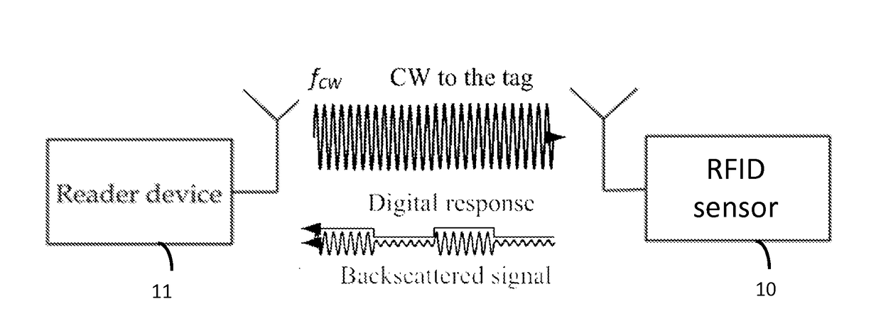
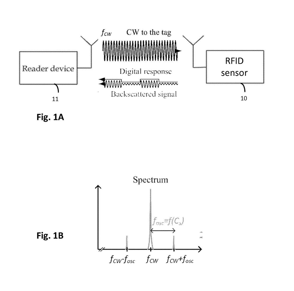
[0041]Referring to FIG. 1A, an RFID system typically comprises two basic components: an RFID transponder or tag 10, which is located on the object to be identified or at a measurement point; an RFID interrogator or reader 11, which performs the interrogation of RFID tags. In a passive RFID system the RFID reader 11 supplies the tag 10 with essential power in order for it to perform modulation of the reader's interrogation signal. In the case of RFID sensor tags, in addition to just providing a power source and medium for the RFID tags 10 to operate and transmit data, an RFID reader 11 may perform data transmission, which is implemented, in most cases, as a modulation of the carrier signal, towards the tags 10.

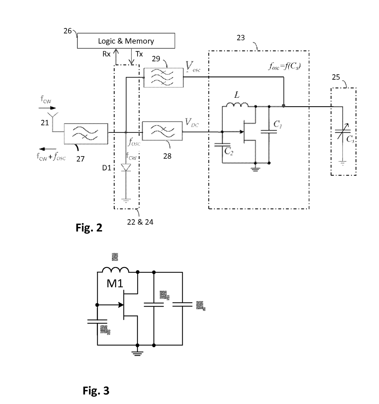
[0042]FIG. 2 shows a functional block diagram illustrating an example of radio frequency identity (RFID) tag architecture. For illustrative purposes, exemplary embodiments of the invention are described with only main parts: an antenna 21, a rectifier 22, an oscillator 23, a mo...


PUM


Abstract

In a RFID sensor tag, a sensing element is connected to an oscillator such that an oscillation frequency of the oscillator is dependent on a value of a predetermined variable sensed by the sensing element. The oscillation frequency of the oscillator is a harmonic multiple N of a modulation frequency required for a backscattering modulator. A frequency divider is arranged at the output of the oscillator to produce the modulation frequency from the oscillation frequency. The oscillator can be designed and dimensioned such that a high sensitivity is obtained with all sensor values, and the desired modulation frequency is derived resulting oscillation frequency by selecting a suitable division ratio N.

Description

FIELD OF THE INVENTION[0001]The present invention relates to passive wireless sensors, particularly passive radio frequency identi cation (RFID) sensors, RFID sensor systems, and RFID readers for passive RFID sensor tags.BACKGROUND OF THE INVENTION[0002]Sensor is a device that transforms a measured quantity into a readable format, typically into an electrical signal. Nowadays, there are commercially available sensors virtually for any measurement purpose. According to the connectivity, sensors can be divided into wireless and wired sensors. Wired sensors are connected via wiring harnesses or cable assemblies to a reader device. Wireless sensors can be read without a physical connection to the sensor, and are often realized equipping the sensor with a radio transceiver. The transmitted radio signal is interpreted by a receiver which converts the wireless signal into a desired output. Wireless operation can be bene cial in many applications, where wired connection is di cult for examp...

Claims


Application Information

Patent Timeline
IPC IPC(8): H04L27/12G06K19/07H04Q9/00
CPCH04L27/12G06K19/0724G06K19/0726H04Q9/00G06K19/0717G06K19/0775G06K19/07775H04Q2209/47G06K7/10198G06K19/0709G06K19/07749
Inventor NIKUNEN, JOONAVIIKARI, VILLE
Owner METSO OUTOTEC (FINLAND) OY
Why Eureka
Try Eureka