

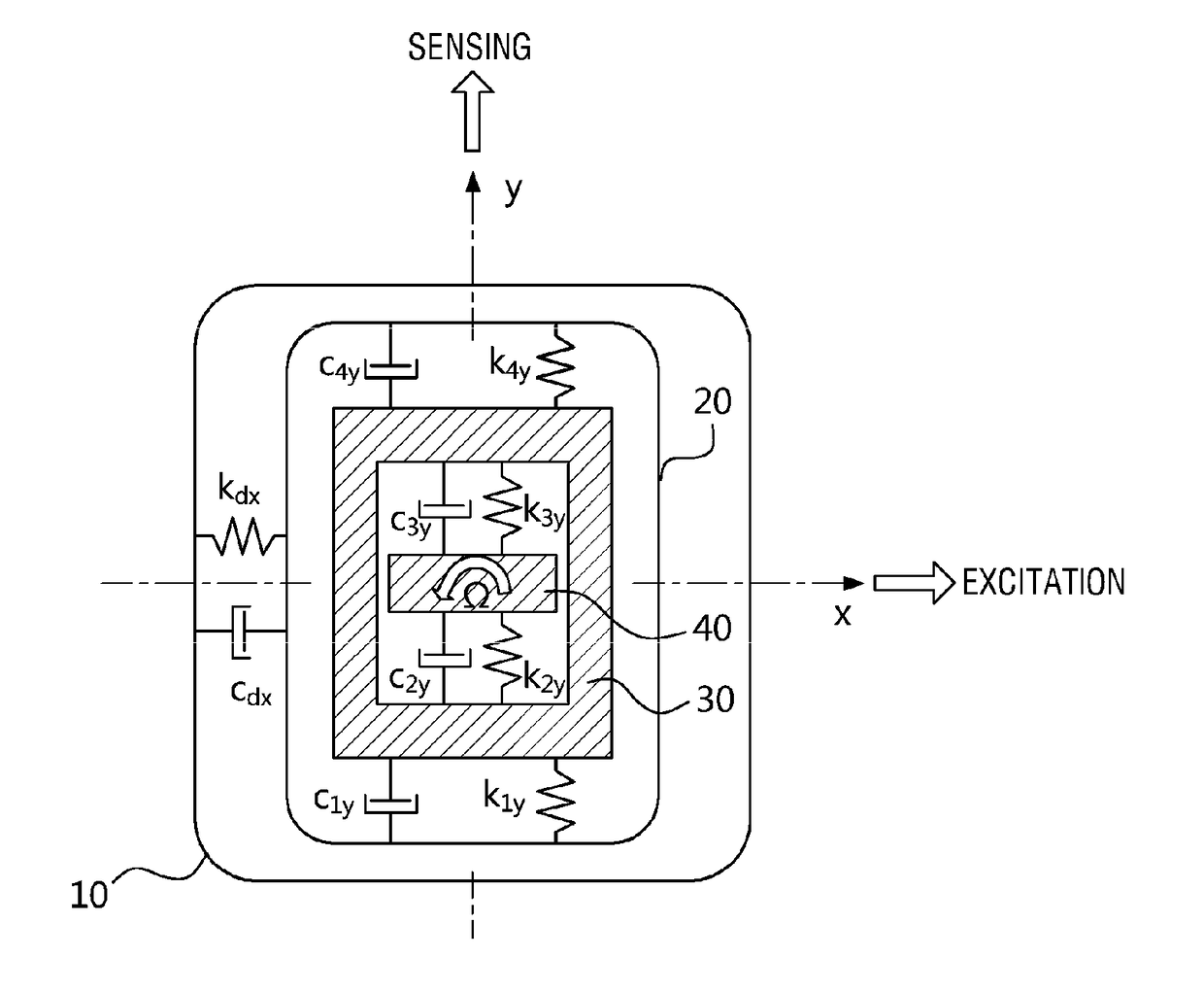
MEMS gyroscope having 2-degree-of-freedom sensing mode
a sensing mode and gyroscope technology, applied in the field of gyroscopes, can solve the problems of reducing the reliability of products, affecting the production efficiency of products, and affecting the quality of products, so as to achieve uniform sensing amplitude and facilitate the manufacture of gyroscopes
- Summary
- Abstract
- Description
- Claims
- Application Information
AI Technical Summary
Benefits of technology
Problems solved by technology
Method used
Image

Examples
Embodiment Construction
[0046]Advantages and features of the present invention and methods of accomplishing the same may be understood more readily by reference to the following detailed description of exemplary embodiments and the accompanying drawings. The present invention may, however, be embodied in many different provides and should not be construed as being limited to the embodiments set forth herein. Rather, these embodiments are provided so that this disclosure will be thorough and complete and will fully convey the concept of the present invention to those skilled in the art, and the present invention will only be defined by the appended claims. Like reference numerals refer to like elements throughout the specification. Furthermore, the expression “and / or”, as used herein, includes any and all combinations of the associated listed words.
[0047]Exemplary embodiments of the present invention will be described with reference to plan views and / or cross-sectional views by way of ideal schematic views....
PUM
 Abstract
Description
Claims
Application Information