Distributed predictive control based voltage restoration scheme for microgrids

a predictive control and micro-grid technology, applied in the field of micro-grid operation and control, can solve the problems of secondary voltage control, complex communication network, huge data-handling, etc., and achieve the effect of avoiding complex communication structure and huge data handling, improving the voltage quality of the micro-grid, and fast and synchronous tracking

Active Publication Date: 2018-05-17
SOUTHEAST UNIV
View PDF0 Cites 19 Cited by
  • Summary
  • Abstract
  • Description
  • Claims
  • Application Information

AI Technical Summary

Benefits of technology

[0005]the technical problem to be solved by the present invention is: providing a distributed predictive control based voltage restoration scheme for microgrids. The control scheme is a completely distributed scheme, realizes the global information, adopts predictive control to acquire a secondary voltage compensation command, and can restore the voltage of each distributed generation in a microgrid. Therefore, the present invention can quickly restore the distributed voltage to the reference value, and improve the overall power quality of a microgrid.Technical Scheme
[0028] Beneficial effects: Compared with the prior art, the present invention has the following beneficial effects: the control scheme in the embodiment of the present invention is a completely distributed control scheme, and avoids the complex communication structure and the huge data handling in a centralized control scheme. To solve the voltage deviation due to the droop primary control, the embodiment of the present invention converts the microgrid secondary voltage restoration problem into a tracker consensus problem based on distributed predictive control, such that the local voltage of each distributed generation can be globally shared, and can quickly and synchronously track the reference value, thus improving the voltage quality of a microgrid. The scheme for restoring microgrid voltage of the present invention acquires the local voltage of each distributed generation via the local agent, establishes a predictive control model comprising a predication term with an adjustable parameter, and expands the predictive control model to a trended prediction model based on HP prediction horizons and HU control horizons. After allocating different weights among the three control targets according to a preset penalty target function to the trended prediction model, the objective of quick voltage restoration among different distributed generations is realized. Acquire the latest secondary compensation term according to the evaluated adjustable prediction coefficient, and implement it on the local controllers. Repeat the steps above until the local voltage values all restore to the reference value. On the condition that not all the distributed generations in a microgrid can acquire the reference value, the global information can be quickly shared by the finite time observer in the embodiment of the present invention. The acquired secondary voltage restoration command comprises prediction information and the results of rolling optimization. Therefore, the present invention has a good adaptability to model uncertainty such as power fluctuations of distributed generations and loads, and plug-and-play of distributed generations. In the embodiment of the present invention, the proposed approach is robust against different information updating rates in the voltage restoration, thus improving the control performance of an islanded microgrid.

Problems solved by technology

However, the droop control is a proportional discriminatory control, and will cause voltage deviation from the reference value, which results to secondary voltage control.
The centralized control scheme is based on a central controller, requires a complex communication network, and suffers from huge data-handling.
Furthermore, the single-point failure and distributed feature of the renewable energy may both result in the change of the communication topology, which further challenge the reliability of the central controller.

Method used


Image

  • Distributed predictive control based voltage restoration scheme for microgrids
  • Distributed predictive control based voltage restoration scheme for microgrids
  • Distributed predictive control based voltage restoration scheme for microgrids

Examples


Embodiment Construction

[0041]In order to enable the objectives, technical schemes and advantages of the present invention to be more apparent, the present invention will be described in more details with the aid of the attached drawing and implementation cases. It should be understood that the specific embodiments described herein are only for illustrating but not for limiting the present invention.

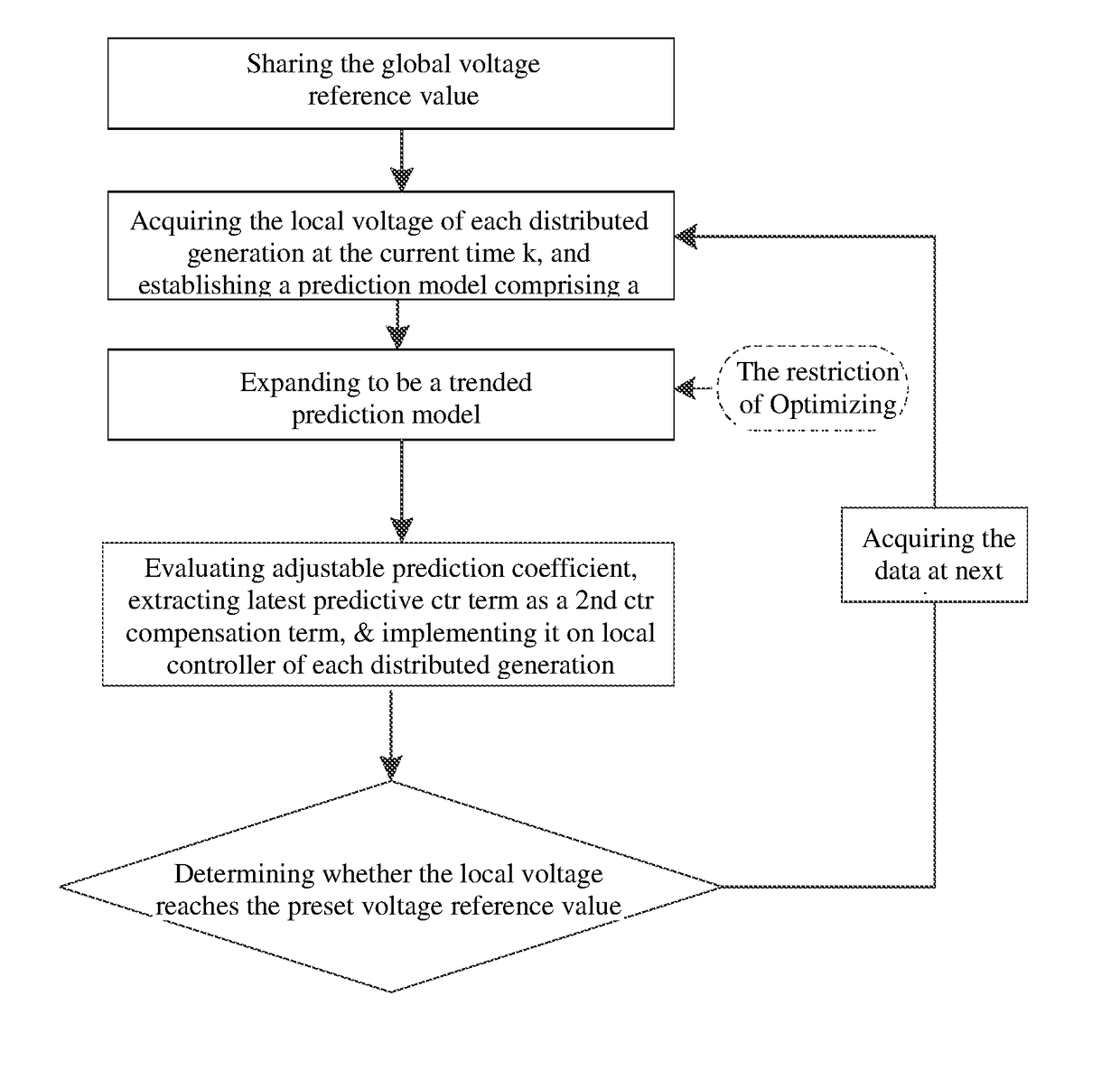
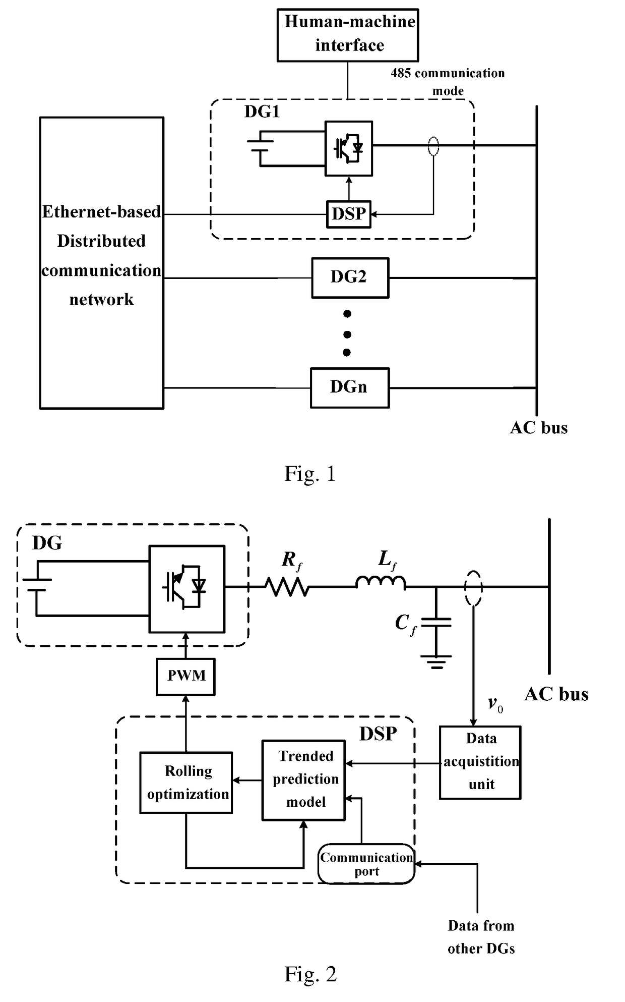
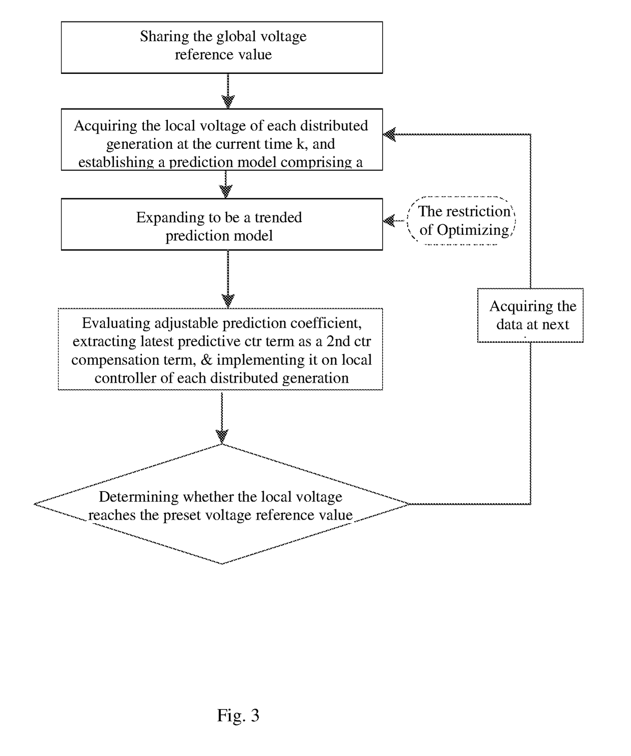
[0042]The control method of the present invention can be applied to a parallel inverter microgrid. As shown in FIG. 1, the microgrid voltage reference instruction is entered through a human-machine interface and sent to the pinned distributed generations via the 485 communication mode. The distributed generations perform information exchange by the Ethernet-based distributed communication network and the diagram of specific signal control and hardware implementation is as shown in FIG. 2. The data acquisition unit of each distributed generation collects the voltage from the local sensor. By combining the local ...


PUM


Abstract

A distributed predictive control based voltage restoration scheme for microgrids, comprising: step 10) adopting a distributed finite time observer to acquire the global reference voltage for restoring the voltage of each local controller; step 20) each local controller adopts a droop control to acquire the local voltage value of each generation, and adds a secondary voltage compensation term into the droop characteristic formula to form the voltage reference value of a distributed generation; step 30) establishing a trended prediction model; step 40) acquiring a predictive control term at a current time as the secondary voltage compensation command, and acting on the local controllers; and step 50) determining, whether the local voltage of each distributed generation of the microgrid reaches the voltage reference value under the secondary voltage compensation command.

Description

[0001]This application is the U.S. national phase of International Application No. PCT / CN2016 / 110483 filed on 16 Dec. 2016 which designated the U.S. and claims priority to Chinese Application Nos. CN201610135626.2 filed on 10 Mar. 2016, the entire contents of each of which are hereby incorporated by reference.TECHNICAL FIELD[0002]The present invention relates to the operation and control of a microgrid, in particular to a distributed predictive control based voltage restoration scheme for microgrids.BACKGROUND[0003]With the gradual exhaustion of resources on the earth and the incensement of serious environmental problems, more and more attentions are drawn to the utilization of renewable energies around the world. Microgrid has emerged as an energy integration to improve the penetration of renewable energy resources and distributed energy resources in an energy supply system. Each microgrid consists of different types of distributed energy resources (DGs) which comprise micro-turbin...

Claims


Application Information

Patent Timeline
Patent Type & Authority Applications(United States)
IPC IPC(8): H02J3/12H02J3/38H02J3/18
CPCH02J3/12H02J3/381H02J3/18H02J3/40H02J2003/388H02J3/388H02J2203/20H02J3/38H02J2310/12H02J2300/10H02J3/14Y02P80/14Y04S20/222Y02B70/3225
Inventor GU, WEILOU, GUANNANCHEN, MINGLIU, WEIXUE, SHUAICAO, GE
Owner SOUTHEAST UNIV
Why Eureka
Try Eureka