
Modular enclosed transportation structure and integrated track assembly

a transportation structure and tube technology, applied in the direction of transportation and packaging, railway track construction, transportation systems, etc., can solve the problems of large diameter tubes requiring special manufacture, limited production capacity, and inability to meet the requirements of transportation systems made of traditional cylindrical tube structures, etc., to achieve the effect of reducing installation costs, reducing labor intensity and reducing labor intensity

Active Publication Date: 2018-05-24
HYPERLOOP TECH INC
View PDF6 Cites 9 Cited by
  • Summary
  • Abstract
  • Description
  • Claims
  • Application Information

AI Technical Summary

Benefits of technology

The patent text describes a new modular structure for building tracks and transportation paths. The lower element of the structure is built off-site and transported to the construction site, making it more efficient and cost-effective compared to large diameter tubes. The upper element can also be shaped on-site or off-site, and the assembled structure decreases construction risks and allows for modular construction. This new structure has many benefits, including faster installation, lower costs, safer working environments, and increased precision. Additionally, it allows for large-scale construction and minimizes the impact on the environment.

Problems solved by technology

Constructing a transportation system made of traditional cylindrical tube structures, however, has limitations.
For example, a tube structure made of steel has several limitations, such as: larger diameter tubes requiring specialized manufacture and a difficult and costly transportation process; and confined space environments (and the increased operational risks that come therewith).
One such limitation, for example, is due to the size of the cylindrical tube itself.
Large diameter cylindrical or elliptical tubes can require specialized manufacturing processes (e.g., expensive rolling, welding and milling).
Due to these specialized manufacturing processes, there are a limited number of suppliers that manufacture large diameter tubes.
This may restrict the locations where a transportation system that utilizes pre-fabricated tubes can feasibly be built.
Additionally, transportation of these large diameter tubes may be problematic due to the size and / or weight of the cylindrical tube section itself.
Furthermore, many countries require permits to move large loads and / or present a small number of available routes for transporting the large tubes.
Roads may need to be blocked during transportation, and transportation of large diameter tubes may require pilot drivers.
As such, with a large tube construction, the possible locations for a transportation system may be limited.
Even if there is a supplier near a proposed development site so that transportation costs are low, however, the tubes will still present a large cost of the project and a barrier to feasible use (e.g., on a cost basis).
Workplaces may contain areas that are considered “confined spaces,” because they are large enough for workers to enter and perform certain jobs, have limited or restricted entry and / or exit routes, and are not designed for continuous occupancy.
Working within confined spaces, such as presented with a tubular structure, can be hazardous (or otherwise dangerous) to employees, which may lead to an increase in insurance and liability costs, increases in operational risks (e.g., accidents, rescue, etc.), and may pose additional health and safety risks.
Additionally, the confined space environments of the tubular structures may slow the rate of assembly.
These confined space environments of tubular structures present an additional limitation of cylindrical tubular structures.
Also, the tubular transportation system may require inserts as supports, which presents a tolerance issue.
Thus, if the inserts are not constructed perfectly, the inserts will not fit properly into the tube.
Such issues present further limitations for cost-effective use of cylindrical tubular structures.
Additionally, due to the circular inner shape of tubular structures, the mounting of levitation and / or guide tracks systems thereto (or therein) imposes significant constrains on construction simplicity, which can slow production rate.
As such, with a tubular construction, track inserts are necessary to provide a track support, which may require a complex extrusion process, and may require painstaking positioning and installation.
For example, concrete inserts may require complex forming and / or molding processes.
Additionally, the inserts add significant non-structural mass to the system.
Furthermore, inserts in the tubular structures may still require post-machining to properly accommodate or house the tracks (e.g., arranged and positioned in an aligned manner).
Thus, the circular inner shape of tubular structures presents another obstacle to cost-effective use of cylindrical tubular structures.
Additionally, these limitations, for example, may be due to dis-integrated installation (e.g., separate tube and track installation) that may make installation and / or positioning times unpractical for large-scale deployment.
For example, separate installation of track and tube increases installation and positioning times and makes achieving the necessary tolerance a highly impractical task.
Moreover, achieving the required tolerance may be a difficult task using standard construction methods.
Furthermore, alignment limitations of large-scale tubular structures (e.g., difficulty of moving and aligning large heavy tubes) may limit employment of the large-scale tubular structures.

Method used


Image

  • Modular enclosed transportation structure and integrated track assembly
  • Modular enclosed transportation structure and integrated track assembly
  • Modular enclosed transportation structure and integrated track assembly

Examples


Embodiment Construction

[0014]The novel features which are characteristic of the disclosure, both as to structure and method of operation thereof, together with further aims and advantages thereof, will be understood from the following description, considered in connection with the accompanying drawings, in which embodiments of the disclosure are illustrated by way of example. It is to be expressly understood, however, that the drawings are for the purpose of illustration and description only, and they are not intended as a definition of the limits of the disclosure.

[0015]The following detailed description illustrates by way of example, not by way of limitation, the principles of the disclosure. This description will clearly enable one skilled in the art to make and use the disclosure, and describes several embodiments, adaptations, variations, alternatives and uses of the disclosure, including what is presently believed to be the best mode of carrying out the disclosure. It should be understood that the d...


PUM


Abstract

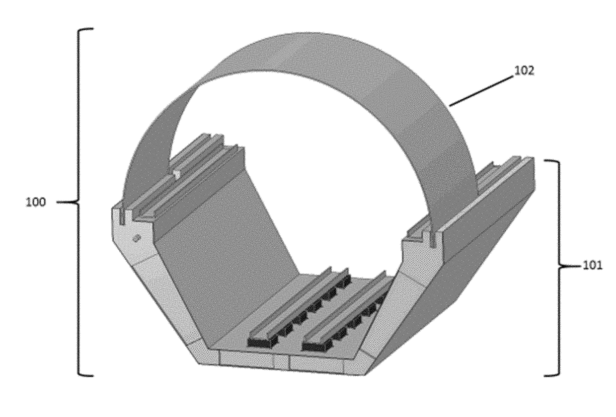
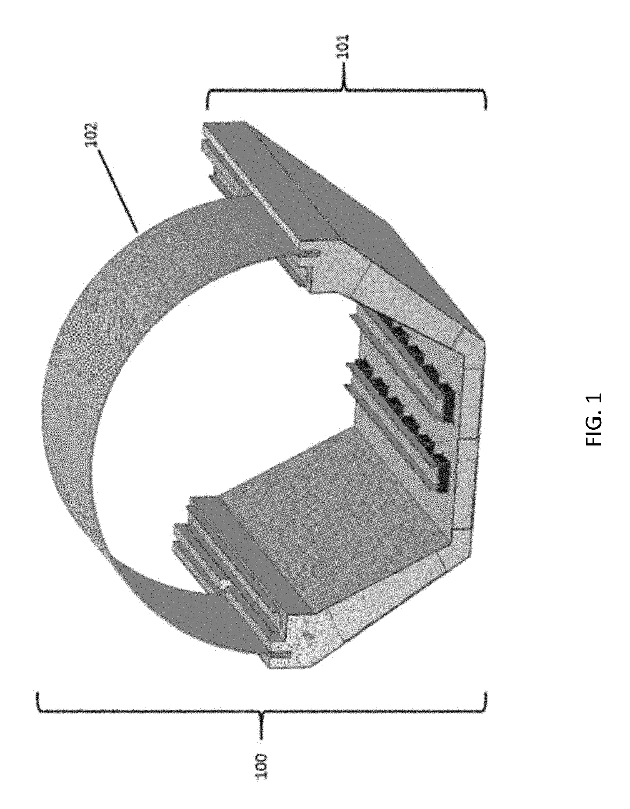
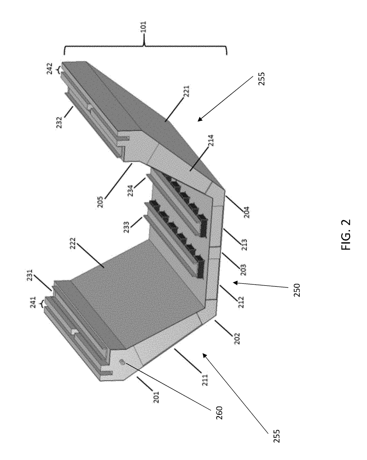
A modular structure, configured to be connectable with a plurality of modular structures to form an enclosed transportation path, each modular structure including a bottom element structured and arranged to provide a track support surface and a plurality of upper element attachment structures, and an upper element configured to attach to the bottom element at the plurality of upper element attachment structures, wherein the upper element is structured to sealingly engage with the lower element.

Description

CROSS-REFERENCE TO RELATED APPLICATIONS[0001]The present application claims the benefit of U.S. Provisional Application No. 62 / 425,749, filed Nov. 23, 2016, and U.S. Provisional Application No. 62 / 471,740, filed Mar. 15, 2017, the contents of which are expressly incorporated herein by reference in their entireties.BACKGROUND OF THE DISCLOSURE1. Field of the Disclosure[0002]The present disclosure relates to an enclosed high-speed transportation system, and more specifically, to a modular enclosed “tube” transportation structure and integrated tube track assembly for a high-speed transportation system.2. Background of the Disclosure[0003]Superstructure tube transportation systems may include solid cylindrical tubes assembled on sliding connections (e.g., at an interface with respective columns or pylons) and connected together to form an enclosed (e.g., low-pressure environment) transportation path environment. A levitation system is installed inside the tube (e.g., in segments) after...

Claims


Application Information

Patent Timeline
IPC IPC(8): B61B13/10B61B13/08E01B29/32
CPCB61B13/10E01B29/32B61B13/08E01B2/00E01B25/00E01B25/30
Inventor ZARAFSHAN, ALI
Owner HYPERLOOP TECH INC
Learn More