Wind turbine blade with a trailing edge spacing section

a technology of trailing edge spacing and wind turbine blade, which is applied in the field of wind turbine blade, can solve the problems that the described prior art approaches do not always provide satisfactory structural stability and support, and achieve the effect of increasing the structural stability of the blad

Active Publication Date: 2018-05-24
LM WP PATENT HLDG
View PDF6 Cites 10 Cited by
  • Summary
  • Abstract
  • Description
  • Claims
  • Application Information

AI Technical Summary

Benefits of technology

[0042]According to another embodiment of the present invention, each spar cap is encapsulated between the inner and outer skin of a shell part, wherein a transition zone is provided between the spar cap and the adjacent intermediate core material of t

Problems solved by technology

It has been found that the above-described prior art approaches do

Method used


Image

  • Wind turbine blade with a trailing edge spacing section
  • Wind turbine blade with a trailing edge spacing section
  • Wind turbine blade with a trailing edge spacing section

Examples


second embodiment

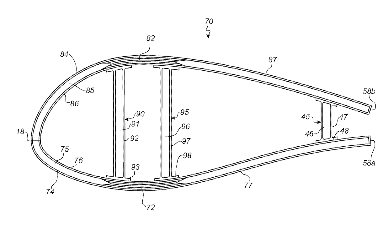
[0061]FIG. 7 shows a trailing edge design of a blade profile according to the invention, and

third embodiment

[0062]FIG. 8 shows a trailing edge design of a blade profile according to the invention.

DETAILED DESCRIPTION

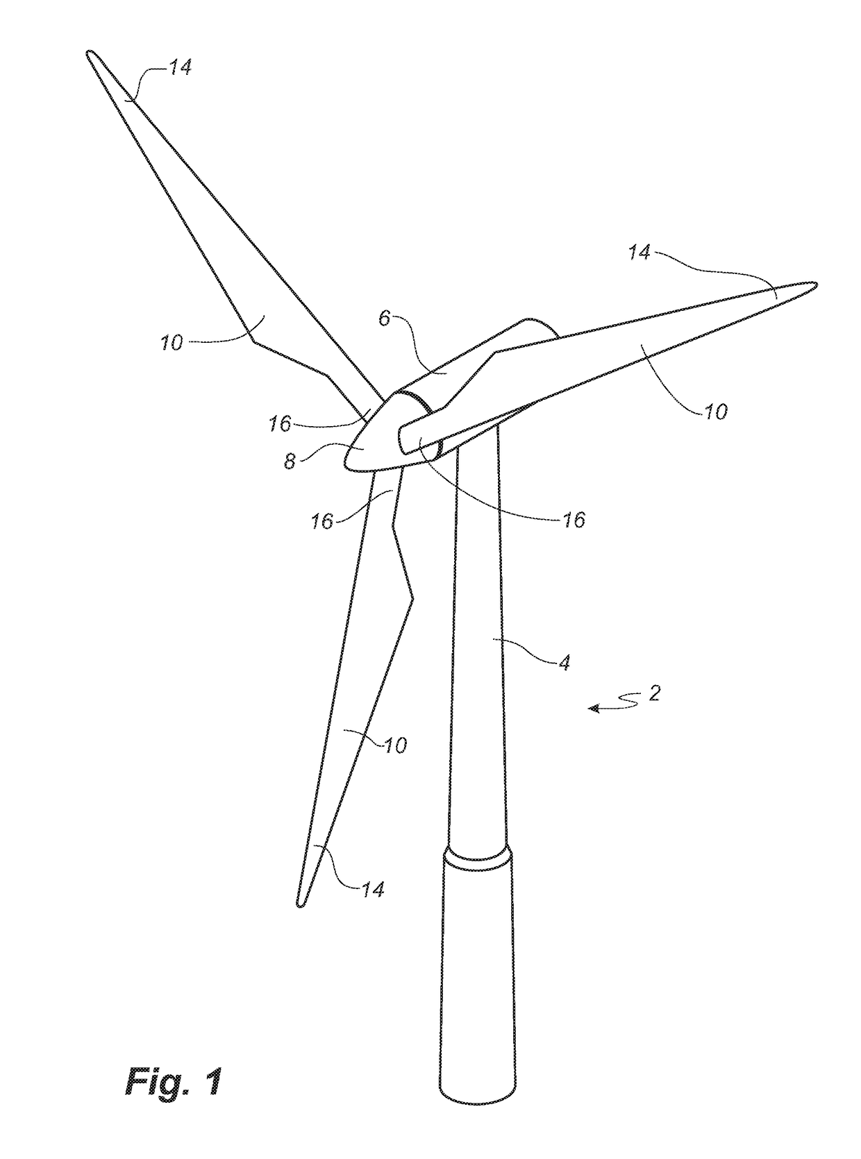
[0063]FIG. 1 illustrates a conventional modern upwind wind turbine according to the so-called “Danish concept” with a tower 4, a nacelle 6 and a rotor with a substantially horizontal rotor shaft. The rotor includes a hub 8 and three blades 10 extending radially from the hub 8, each having a blade root 16 nearest the hub and a blade tip 14 furthest from the hub 8. The rotor has a radius denoted R.

first embodiment

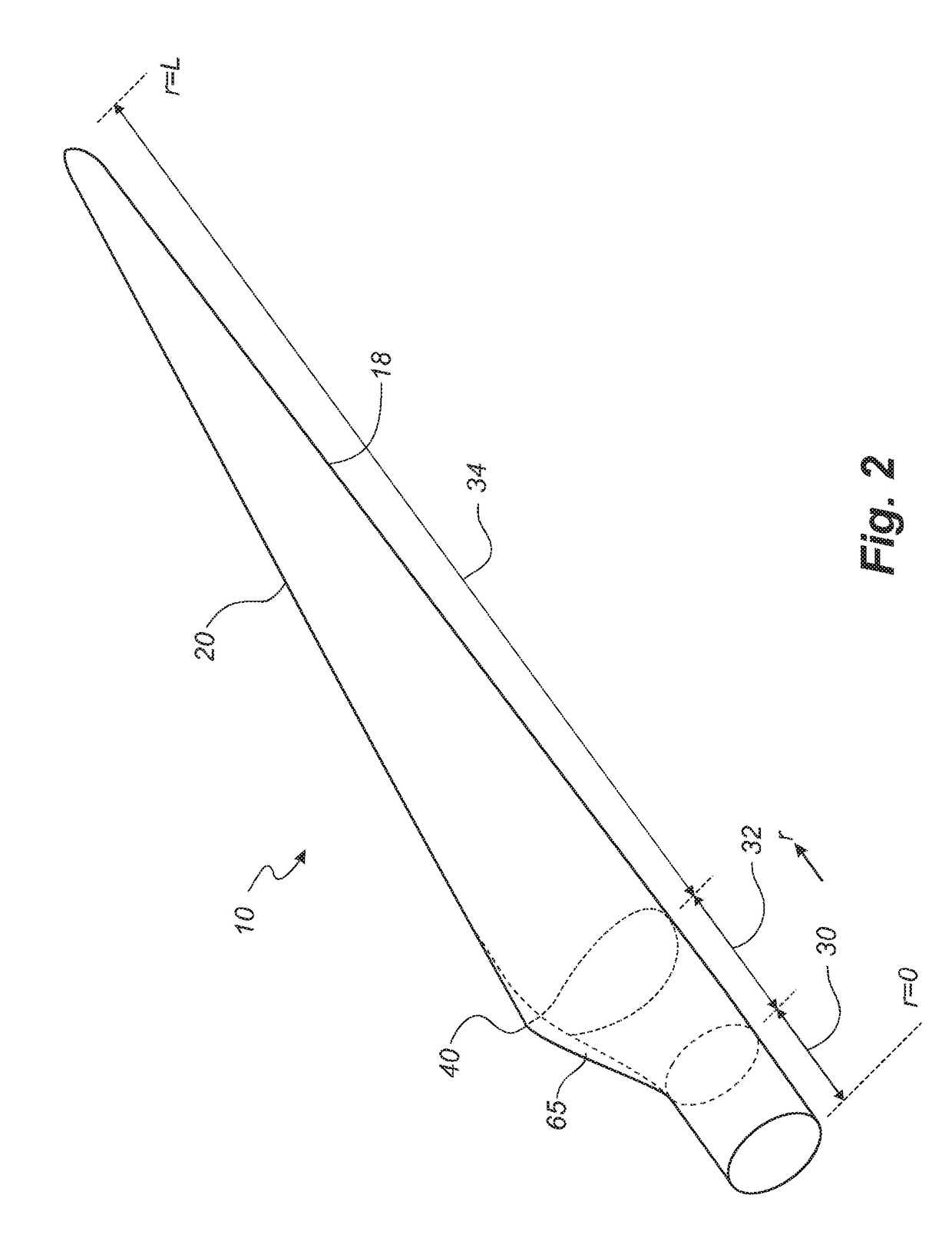
[0064]FIG. 2 shows a schematic view of a wind turbine blade 10 according to the invention. The wind turbine blade 10 has the shape of a conventional wind turbine blade and comprises a root region 30 closest to the hub, a profiled or an airfoil region 34 furthest away from the hub and a transition region 32 between the root region 30 and the airfoil region 34. The blade 10 comprises a leading edge 18 facing the direction of rotation of the blade 10, when the blade is mounted on the hub, and a trailing edge 20 facing the opposite direction of the leading edge 18.

[0065]The airfoil region 34 (also called the profiled region) has an ideal or almost ideal blade shape with respect to generating lift, whereas the root region 30 due to structural considerations has a substantially circular or elliptical cross-section, which for instance makes it easier and safer to mount the blade 10 to the hub. The diameter (or the chord) of the root region 30 may be constant along the entire root area 30. ...


PUM


Abstract

A wind turbine blade is provided with two shell parts each at least partly made of a sandwich structure including an inner skin (76), an outer skin (74), and an intermediate core material (75, 77), wherein the shell parts are bonded together at least along their respective leading edges (18). The blade also comprises a longitudinally extending spacing section in which the respective trailing edges (58a, 58b) of the pressure side shell part and the suction side shell part are spaced apart, wherein a trailing edge shear web (45) is arranged between and connected to the sandwich structure of the suction side shell part (84, 86, 87) and the sandwich structure of the pressure side shell part (74, 76, 77).

Description

FIELD OF THE INVENTION[0001]The present invention relates to a wind turbine blade with a spacing section at its trailing edge providing improved aerodynamic properties and structural stability.BACKGROUND OF THE INVENTION[0002]Modern wind turbines must be designed to withstand extreme loads, hostile environments and harsh weather conditions during their entire lifetime. This applies in particular to turbine blades which are the major elements for converting wind energy into electrical energy.[0003]Wind turbine blades used for horizontal axis wind turbines can be rather large and may today exceed 70 metres in length and 4 metres in width. The blades are typically made from a fibre-reinforced polymer material and comprise a pressure side shell part and a suction side shell part. The cross-sectional profile of a typical blade includes an airfoil for creating an air flow leading to a pressure difference between both sides. The resulting lift force generates torque for producing electrici...

Claims


Application Information

Patent Timeline
IPC IPC(8): F03D1/06
CPCF03D1/0641F03D1/0633F03D1/0675Y02E10/72Y02P70/50
Inventor GARM, JESPER HASSELBALCH
Owner LM WP PATENT HLDG
Why Eureka
Try Eureka