Method of manufacturing liquid crystal display device and manufacturing system for liquid crystal display device
a manufacturing system and liquid crystal display technology, applied in the direction of optics, instruments, non-linear optics, etc., can solve the problems of inability to accurately measure the gap, the deformation of the columnar spacer may be hardly, and the spacer beads may adversely be arranged, etc., to achieve the effect of high yield ra
- Summary
- Abstract
- Description
- Claims
- Application Information
AI Technical Summary
Benefits of technology
Problems solved by technology
Method used
Image
Examples
first preferred embodiment
[0047](Configuration of Liquid Crystal Panel)
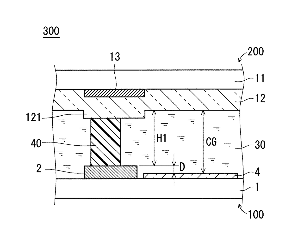
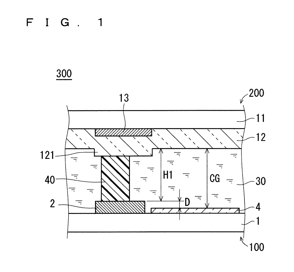
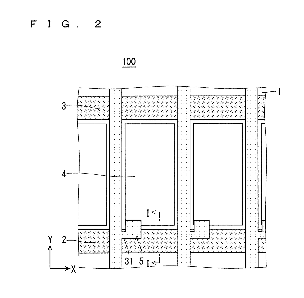
[0048]FIG. 1 is a view for schematically illustrating configuration of a liquid crystal panel 300 of a liquid crystal display device according to this preferred embodiment, specifically, a partial sectional view taken along the line I-I of FIG. 2 and FIG. 3. FIG. 2 is a partial plan view for schematically illustrating configuration of the TFT substrate 100 of the liquid crystal panel 300. FIG. 3 is a partial plan view for schematically illustrating configuration of the CF substrate 200 of the liquid crystal panel 300. The liquid crystal panel 300 includes the CF substrate 200 (first substrate) and the TFT substrate 100 (second substrate) that oppose each other through intermediation of the cell gap CG, the columnar spacers 40 for retaining the cell gap CG, and the liquid crystal layer 30 inside the cell gap CG.
[0049]The TFT substrate 100 includes a transparent substrate 1, gate wirings 2, source wirings 3, a pixel electrode 4, and a TFT 5...
second preferred embodiment
[0089]In the first preferred embodiment, as illustrated in FIG. 5, description is given to the case where one type of columnar spacer is used. In this preferred embodiment, description is given to the case of a dual spacer structure as illustrated in FIG. 8. In the dual spacer structure, the high-temperature gap unevenness is mainly related to the columnar spacer 40, and the low-temperature bubbling is mainly related to the sub-columnar spacer 41.
[0090]FIG. 14 is a graph for showing an example of a method of calculating the amount of the liquid crystal according to this preferred embodiment. In FIG. 14, for the purpose of obtaining a comprehensive graph that corresponds to the dual spacer structure, a horizontal axis is represented with use of the height H0 of the columnar spacer 40 (FIG. 8). The height H0 of the columnar spacer 40 is converted into a height of the sub-columnar spacer 41 (FIG. 8) by subtracting a dimensional difference provided at the time of designing. The dimensio...
third preferred embodiment
[0099]FIG. 16 is a graph for showing an example of a method of calculating the amount of the liquid crystal according to this preferred embodiment. In the height range R3, as a determination function Q3, an intermediate value of the cell-gap upper limit LU and the cell-gap lower limit LL is used. In the height range R1 and the height range R2, as the determination function Q3, values that are different from the above-mentioned intermediate value are used. Specifically, in the height range R1, in order to preferentially arrange a dispersion upper limit DU3 not to exceed the high-temperature limit BH, such a linear function is used that an allowance corresponding to the dispersion of 0.05 μm is secured with respect to the high-temperature limit BH. In the height range R2, in order to preferentially arrange a dispersion lower limit DL3 not to exceed the low-temperature limit BL, such a linear function is used that an allowance corresponding to the dispersion of 0.05 μm is secured with ...
PUM
| Property | Measurement | Unit |
|---|---|---|
| Temperature | aaaaa | aaaaa |
| Height | aaaaa | aaaaa |
| Optical properties | aaaaa | aaaaa |
Abstract
Description
Claims
Application Information
 - R&D
- Intellectual Property
- Life Sciences
- Materials
- Tech Scout
- Unparalleled Data Quality
- Higher Quality Content
- 60% Fewer Hallucinations
Browse by: Latest US Patents, China's latest patents, Technical Efficacy Thesaurus, Application Domain, Technology Topic, Popular Technical Reports.
© 2025 PatSnap. All rights reserved.Legal|Privacy policy|Modern Slavery Act Transparency Statement|Sitemap|About US| Contact US: help@patsnap.com


