Vane pump and method for the operation thereof

a technology of a vane cell and a valve body, which is applied in the direction of pump control, rotary piston liquid engine, engine components, etc., can solve the problems of difficult operation conditions, pressure build-up almost completely coming to a standstill, and significant limited conveying capacity, so as to reduce inner losses and reduce wear.

Active Publication Date: 2018-05-31
HANON SYST EFP DEUT GMBH
View PDF4 Cites 0 Cited by
  • Summary
  • Abstract
  • Description
  • Claims
  • Application Information

AI Technical Summary

Benefits of technology

[0019]An object of the invention is to develop a hydraulic vane cell pump which can be operated in an energy-saving manner with a simple constructional structure and a high level of operational reliability under any operating conditions and a method which ensures an energy-saving operation of a structurally simply constructed vane cell pump which is reliable under any operating conditions.
[0037]The conveying elements are already in the moved-in state in a position which is nearer the contour of the contour ring so that a more rapid starting with a smaller stroke is possible.
[0038]Since no additional component is required in the pump, the small construction space of the inner ring is advantageous and can also be fitted in the structural space of a conventional pump.

Problems solved by technology

This results in the already significantly limited conveying capacity and resultant pressure build-up almost completely coming to a standstill.
Furthermore, there may occur more difficult operating conditions which additionally arise in combination with the regularly occurring cold start of a hydraulic vane cell pump with highly viscous oil and which can thereby exacerbate this.
A first difficult operating condition is a cold start after previous air intake.
A second difficult operating condition involves restarting a hydraulic vane cell pump which is driven by a fixedly coupled output shaft of a periodically operating thermal engine, wherein in the event of the above deactivation, as a result of the periodic nature of the thermal engine, an unintentional blowback occurs, together with a backward rotation of the vane cell pump.
A third difficult operating condition involves restarting an electromotively driven hydraulic vane cell pump which is controlled as required and which has previously been operated for the purposes of moving in the conveying elements intentionally with backward rotation and / or driven with unintentional slow rotation and / or depending on requirements is intended to be operated at a low speed.
A disadvantage with hydraulic vane cell pumps in which the expulsion of the conveying elements against the inner peripheral face of the contour ring takes place exclusively with hydraulic support of the action of centrifugal force is the unsatisfactory conveying capacity thereof when starting up under the difficult operating conditions set out, including restarting after the fluid has cooled.
The disadvantage of this is the high degree of wear as a result of the clamping forces acting constantly between the control cam and conveying elements and between the conveying elements and the inner peripheral face of the contour ring.
Furthermore, the service-life is significantly limited as a result of the resilient elements which are used, such as, for instance, elastomer materials.
The disadvantage of this is the limited service-life as a result of ageing of the elastomer ring.
A disadvantage therein involves friction losses which are increased in comparison with an exclusively hydraulic expulsion of the conveying elements against the inner peripheral face of the contour ring during continuous operation in conjunction with an increased level of wear because the conveying elements are resiliently loaded by the clamping ring against the inner peripheral face of the contour ring in addition to the centrifugal force and in addition to the pump pressure.
Furthermore, the service-life which is limited only by occurrences of fatigue of the clamping ring is disadvantageous.

Method used


Image

  • Vane pump and method for the operation thereof
  • Vane pump and method for the operation thereof
  • Vane pump and method for the operation thereof

Examples


Embodiment Construction

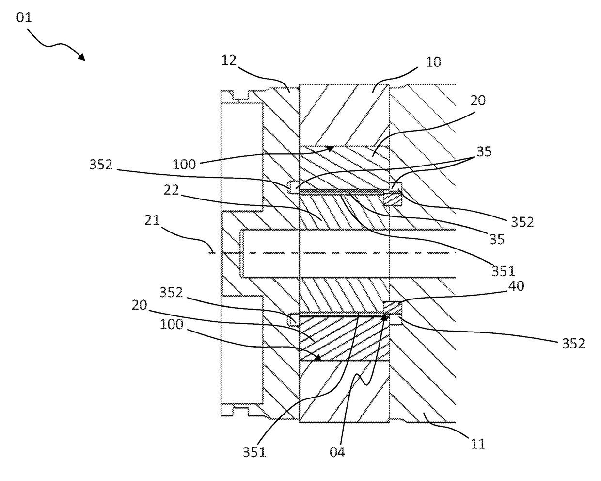
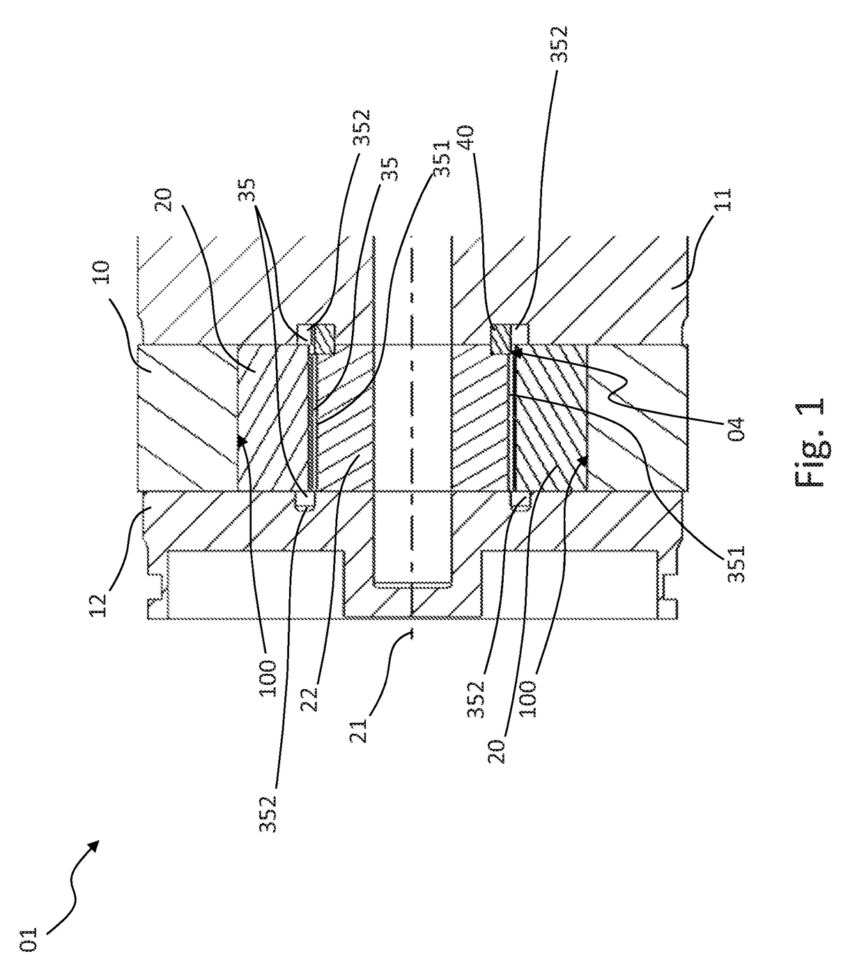
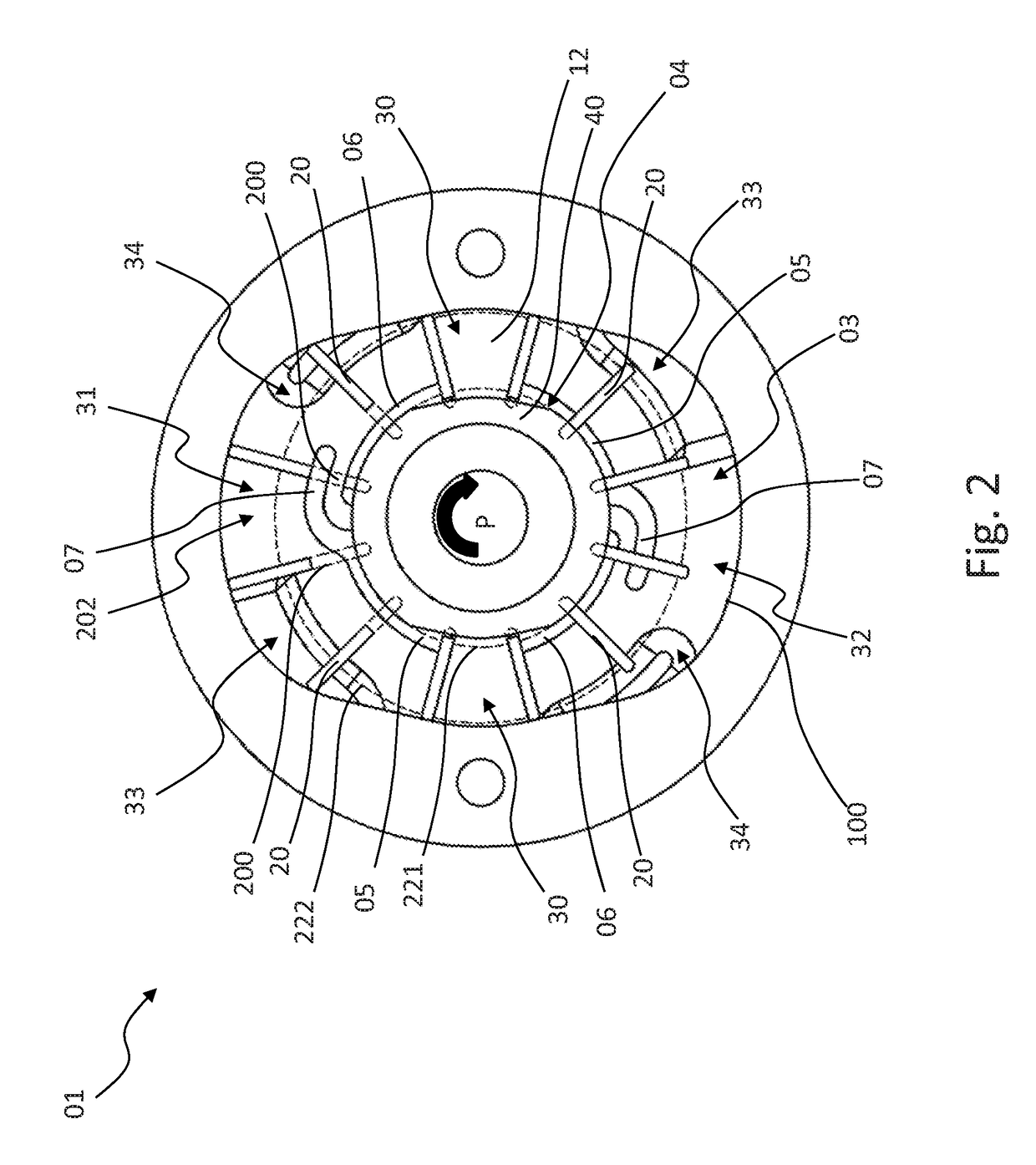
[0055]A vane cell pump 01 illustrated completely or partially in FIGS. 1 to 9 comprises:[0056]a hollow-cylindrical contour ring 10 which is arranged between two side plates 11, 12 and which has an inner peripheral face 100 and[0057]a rotor 22 which is rotatably supported about a rotation axis 21 which extends parallel with the cylinder axis of the contour ring 10 and which has a plurality of conveying elements 20 which can be displaced radially relative to the rotation axis 21 and which are urged against the inner peripheral face 100 during a rotation of the rotor 22.

[0058]The rotation axis 21 of the rotor 22 is a geometric axis. The rotor 22 may, for example, be rotatably supported on a shaft which extends along such a geometric axis or on one of the two side plates 11, 12 or on both of the side plates 11, 12, or it can be connected to a shaft which is supported about such a geometric axis and which extends along this axis.

[0059]The inner peripheral face 100 is constructed in such ...


PUM


Abstract

There are described a vane cell pump and a method for operating a vane cell pump. The vane cell pump comprises a hollow-cylindrical contour ring which is arranged between two side plates and which has an inner peripheral face and a rotor which is rotatably supported about a rotation axis which extends parallel with the cylinder axis of the contour ring and which has a plurality of conveying elements which can be displaced radially relative to the rotation axis and which are urged against the inner peripheral face during a rotation of the rotor. The inner peripheral face is formed in such a manner that a number corresponding to the number of flows of the vane cell pump in respect of pump portions are each constructed with an intake region and a pressure region which are passed through by the conveying elements during a rotation of the rotor. Within a pump portion, the radial spacing between the rotation axis and the inner peripheral face increases when viewed in the working rotation direction of the rotor over the intake region in order subsequently to decrease toward the end of the pressure region again. A narrow location, during the passage through which the conveying elements (are displaced radially inward toward the rotation axis to the greatest extent, is located between a pressure region) and a subsequent intake region when viewed in the working rotation direction. The rotor has, radially inside the conveying elements, expulsion regions which are at least partially connected to at least one pressure region via a fluid path in order to expel the conveying elements against the inner peripheral face. By applying only a part-stroke, an auxiliary start contour which is arranged between the rotation axis and the inner peripheral face radially inside the conveying elements in the region of at least one pump portion displaces conveying elements which are previously displaced at a narrow location to the greatest extent radially inwardly toward the rotation axis as a result of a maximum of temporary contact into the pump portion.

Description

CROSS-REFERENCE TO RELATED APPLICATIONS[0001]This application is a National Stage of International Application No. PCT / EP2016 / 061611, filed May 23, 2016, which claims priority to German Application No. 102015210209.2 filed Jun. 2, 2015. The entire disclosure of each of the above applications is incorporated herein by reference.FIELD OF THE INVENTION[0002]The invention relates to a vane cell pump comprising a hollow-cylindrical contour ring which is arranged between two side plates and which has an inner peripheral face and a rotor which is rotatably supported about a rotation axis which extends parallel with the cylinder axis of the contour ring and which has a plurality of conveying elements which can be displaced radially relative to the rotation axis and which are urged against the inner peripheral face during a rotation of the rotor and a method for the operation thereof, which provides for at least the conveying elements which are still completely moved in during a rotation of ...

Claims


Application Information

Patent Timeline
Patent Type & Authority Applications(United States)
IPC IPC(8): F04C2/344F01C21/08F04C14/06F01C21/10
CPCF04C2/3446F01C21/0863F01C21/0836F04C14/06F01C21/108F04C2240/20F04C2270/701
Inventor BORCHERS, DIRKDIPPEL, THOMAS
Owner HANON SYST EFP DEUT GMBH
Why Eureka
Try Eureka