Cleaning blade

a technology of cleaning blades and blades, applied in the field of cleaning blades, can solve the problems of difficult stabilization of volume electric resistance, difficult scraping of residual toner into a toner recovery box utilizing rubber elasticity, and inability to store toner in the toner recovery box, etc., to achieve the effect of inhibiting the increase of contact electrical resistance, not impairing the reactivity of urethane catalysts, and high adhesion

Inactive Publication Date: 2018-05-31
SUMITOMO RIKO CO LTD
View PDF2 Cites 0 Cited by
  • Summary
  • Abstract
  • Description
  • Claims
  • Application Information

AI Technical Summary

Benefits of technology

[0010]However, because the dispersion state of a carbon black is difficult to control, it is difficult to stabilize the volume electric resistance in the blade par t. Further, the carbon black added to the blade part makes the compression set arid permanent elongation of the blade part worse, and increases the hardness of the blade part. Thus, the rubber elasticity of the polyurethane rubber is impaired, which causes troubles in scraping off of the toner.
[0011]On the other hand, if an ion liquid is added to the blade part, bleeding tends to be caused. There arises a problem in that the bleeding of the ion liquid would contaminate the counterpart member. Besides,, common ion conductive agents such as lithium bis(trifluoromethanesulfonyl) imide (LiTFSI) and lithium bis(fluorosulfonyl) imide (LiFSI) deteriorate the reactivity of a urethane catalyst in forming the blade part. For this reason, under producing conditions as conventionally applied, the curability of the blade part is lowered to thereby deteriorate the adhesiveness of the blade part to the plate-shaped portion. Therefore, it is not possible to produce a cleaning blade that is able to scrape off the residual toner while destaticizing the residual toner.
[0019]In the cleaning blade, a potassium salt is contained in the blade part within the specific range as mentioned above, so that the potassium salt as an ion conductive agent can be inhibited from bleeding and / or blooming on the surface of the blade part. Accordingly, the cleaning blade hardly contaminates the counterpart member. In addition, the potassium salt tends not to impair the reactivity of a urethane catalyst unlike the ion conductive agents such as LiTFSI and LiFSI. For this reason, in the cleaning blade, even under the producing conditions as conventionally applied, the blade part, can be allowed to be cured, to surely obtain the adhesiveness to the plate shaped portion, and to fully bring out the rubber elasticity of the polyurethane rubber. Further, in the cleaning blade, because the blade part has high adhesion with the plate-shaped portion and the conductive adhesion layer, floating resulted front peeling in the boundary face between the blade part and the conductive adhesion layer hardly occurs during operation of the cleaning blade. Thus, in the cleaning blade, it is made possible to inhibit an increase of a contact electrical resistance between the blade part and the conductive adhesion layer. In this way, in the cleaning blade, a conductive path composed of the blade part, the conductive adhesion layer, and the conductive support can be surely established. Accordingly, when installed in the image forming device in a grounded state, the cleaning blade can scrape off and remove the toner utilizing the rubber elasticity of the polyurethane rubber in the blade part while destaticizing the residual toner.
[0020]Thus, according to the present disclosure, there can be provided a cleaning blade that hardly contaminates a counterpart member, hardly impairs the reactivity of a uretharic catalyst, and is able to scrape off a residual toner while destaticizing the residual toner.

Problems solved by technology

Thus, it has become difficult to efficiently scrape off the residual toner into a toner recovery box utilizing rubber elasticity of the blade part.
Consequently, in some cases, the toner cannot be stored in the toner recovery box and may flow over from the toner recovery box.
However, because the dispersion state of a carbon black is difficult to control, it is difficult to stabilize the volume electric resistance in the blade par t. Further, the carbon black added to the blade part makes the compression set arid permanent elongation of the blade part worse, and increases the hardness of the blade part.
Thus, the rubber elasticity of the polyurethane rubber is impaired, which causes troubles in scraping off of the toner.

Method used


Image

  • Cleaning blade
  • Cleaning blade
  • Cleaning blade

Examples


embodiment 1

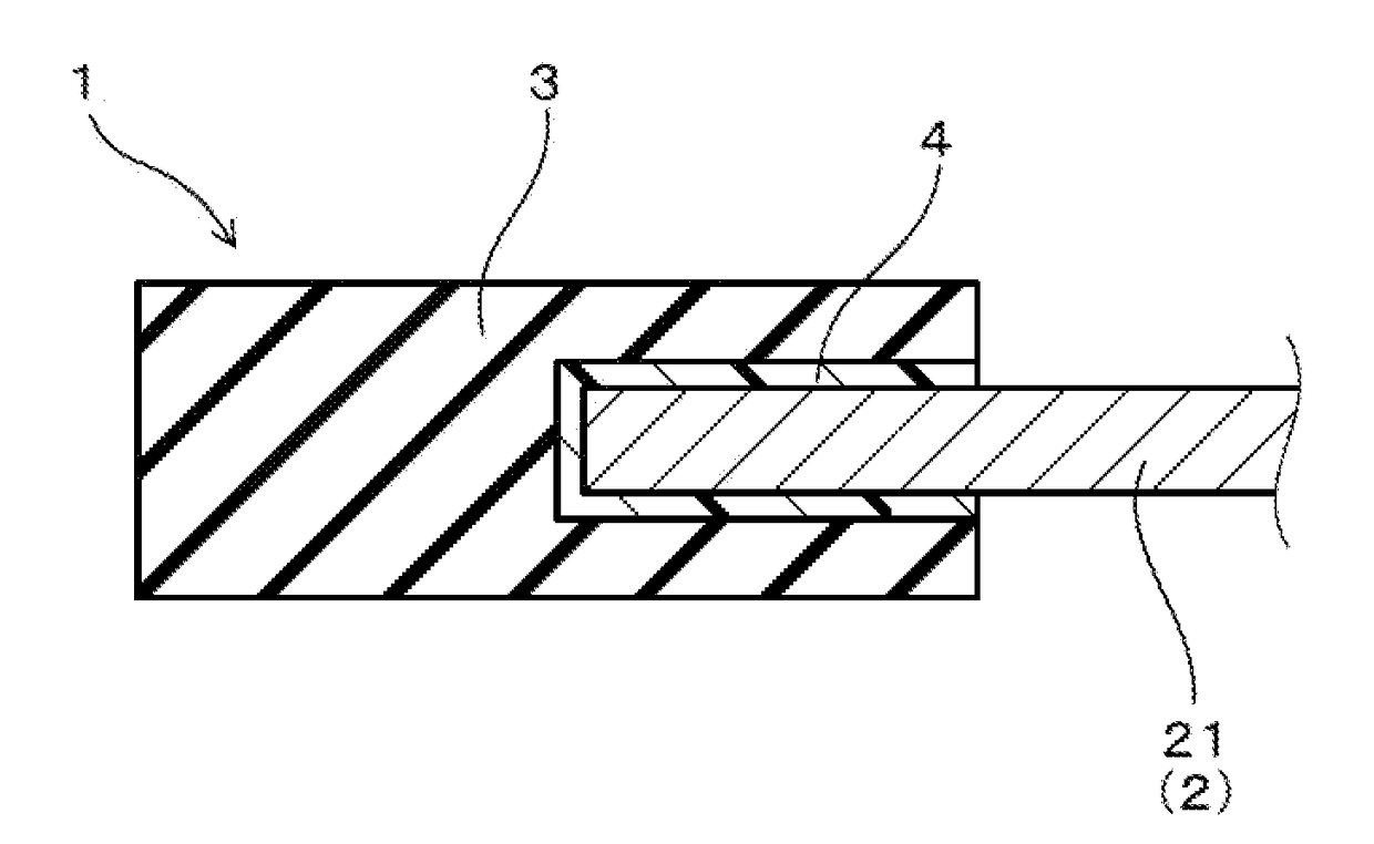
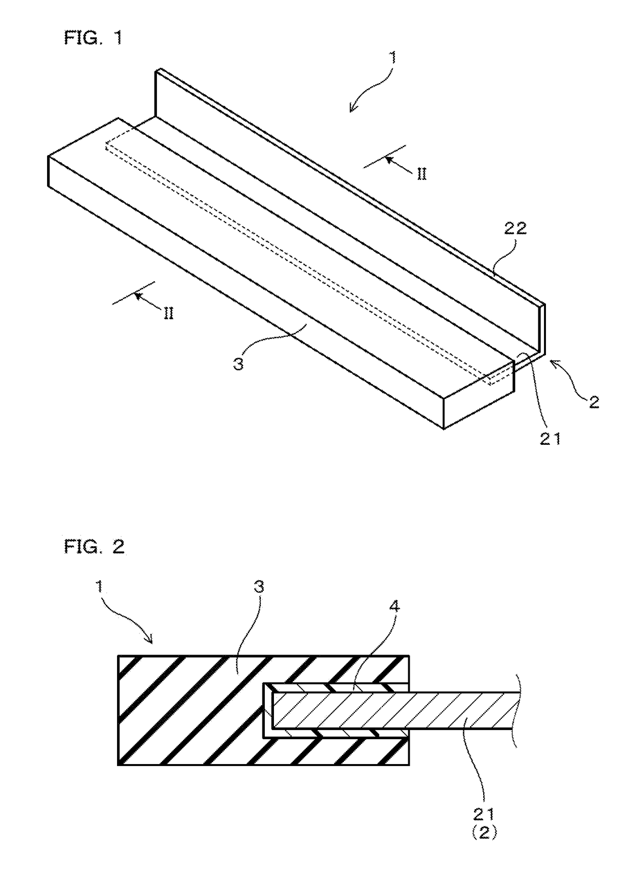
[0040]A cleaning blade according to Embodiment 1 will be described with reference to FIGS. 1 and 2. As illustrated in FIGS. 1 and 2, a cleaning blade 1 of the present embodiment is a cleaning blade for use to remove a residual toner (including not only a toner but also a toner external additive) remaining on the surface of a counterpart member in an electrophotographic image forming device by sliding contact with the counterpart member 1. In the present embodiment, the counterpart member is specifically a photoreceptor drum in an electrophotographic image tensing device.

[0041]The cleaning blade 1 has a conductive support 2 including a plate-shaped portion 21, a blade part 3 that is formed on the plate-shaped portion 21, and is made of polyurethane rubber, and a conductive adhesion layer 4 that is provided between the plate-shaped portion 21 and the blade part 3, and contains a conductive agent (not shown in figures). The blade part 3 contains a potassium salt (not shown in figures) ...

embodiment 2

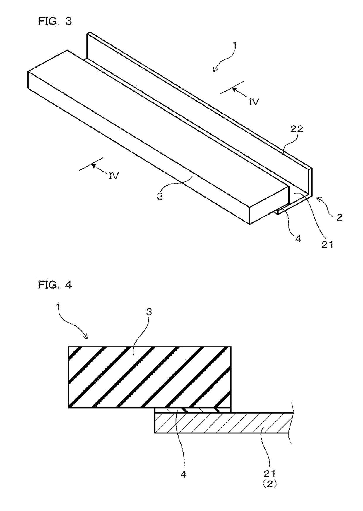
[0043]A cleaning blade according to Embodiment 2 will be described with reference to FIGS. 3 and 4. As illustrated in FIGS. 3 and 4, in the cleaning blade 1 of the present embodiment, the blade part 3 is bonded on one plate surface of the plate-shaped portion 21. The conductive adhesion layer 4 is provided between the one plate surface of the plate-shaped portion 21 and a part of the blade part 3 which opposes to the one plate surface. Other configurations are the same as those disclosed in Embodiment 1.

[0044]Hereinafter, the present disclosure will be described more specifically with reference to an experimental example.

—Preparation of Urethane Rubber Compositions—

[0045]Forty four parts by mass of polybutylene adipate (PBA) (“Nippolan 4010” manufactured by Tosoh Corporation) subjected to defoaming in vacuum at 80° C. for 1 hour, and 56 parts by mass of 4,4-diphenylmethane diisocyanate (MDI) (“Millionate MT” manufactured by Tosoh Corporation) were mixed, and reacted under a nitrogen...


PUM


Abstract

Provided is a cleaning blade to be used for removing a residual toner that remains on a surface of a counterpart member in an electrophotographic image forming device, by sliding contact with the counterpart member. The cleaning blade includes a conductive support including a plate-shaped portion; a blade part that is formed on the plate-shaped portion and is made of a polyurethane rubber; and a conductive adhesion layer that is provided between the plate-shaped portion and the blade part and contains a conductive agent. In the cleaning blade, the blade part contains a potassium salt in an amount of 0.3 mass % or more and less than 10 mass %, and the potassium salt includes at least one kind of anion selected from the group consisting of CF3SO2C4F9SO2N−, (CF3SO2)2N−, (FSO2)N−, C28H28BO6−, AlCl4−, Al2Cl7−, NO3−, BF4−, PF6−, CF3COO−, CF3SO3−, (CF3SO2)3C−, AsF6−, SbF6×, F(HF)N−, CF3CF2CF2CF2SO3−, (CF3CF2SO2)2N−, CF3CF2CF2COO−, (C4F9SO2)2N−, CF2(CF2SO2)2N− and CF3SO2NH2−.

Description

CROSS-REFERENCE[0001]This application is a Continuation of International Application No. PCT / JP2016 / 074674 filed on Aug. 24, 2016, which claims priority to Japanese Patent Application No. 2015-192404 filed on Sep. 30, 2015. The entire contents of which are incorporated herein by reference.TECHNICAL FIELD[0002]The present disclosure relates to a cleaning blade, and more particularly to a cleaning blade for use in an electrophotographic image forming device.BACKGROUND ART[0003]In an electrophotographic image forming device, a cleaning blade is employed to clean, for instance, the surface of an image bearing member such as a photoreceptor or an intermediate transfer belt. The cleaning blade has a blade part, of which the front edge portion is pressed onto the surface of the image bearing member or the intermediate transfer belt as a counterpart member. A residual toner that remains on the surface of the counterpart member is scraped off and removed by sliding contact between the counte...

Claims


Application Information

Patent Timeline
Patent Type & Authority Applications(United States)
IPC IPC(8): G03G21/00
CPCG03G21/0017
Inventor NIMURA, YASUNORISUZUKI, SATOSHIYAMAGUCHI, KAZUSHI
Owner SUMITOMO RIKO CO LTD
Why Eureka
Try Eureka