Wearable motion tracking system

a motion tracking and wearable technology, applied in the field of wearable motion tracking systems, can solve the problems of lowering the appeal of such systems in home consumer products, affecting the use of users, and the required calibration is clearly not suitable for non-professional applications, and achieves the effect of stable and reliable, fast measuremen

Active Publication Date: 2018-05-31
SENSORYX AG
View PDF2 Cites 7 Cited by
  • Summary
  • Abstract
  • Description
  • Claims
  • Application Information

AI Technical Summary

Benefits of technology

[0026]In some embodiments, said plurality of measurements between said first measurement device and said second measurement device comprises at least one direction measurement between said first measurement device and said second measurement device. In these embodiments, the direction measurement results, in combination with the distance measurement, directly in the position in three dimensions of the second measurement device with respect to the first measurement device. So the present teaching already works with two sensors and two measurements between the first and the second measurement device. This is advantageous, as fewer beacons, less hardware and less computation are required in comparison to known approaches.
[0027]Moreover, the present invention does not require complex sensor fusion algorithms as extended Kalman filters or the like, to combine measurements from multiple sensors and sensor types. The measurements taken by the system according to invention (e.g. one distance measurement by e.g. an acoustic receiver / emitter pair and one direction measurement by e.g. an optical receiver / emitter pair) can be used to directly eliminate all degrees of freedom and compute directly the relative position between the first and second measurement device without requiring any other third or fourth sensor device. This results in less computation, less latency and more stability. To give an example: in order to estimate the hand position relative to the head, according to known approaches, one requires one sensor on the head, one on the hand and two more on the head or other body parts (which is cumbersome to wear) while according to some embodiments of the invention, only one measurement device on the head and one on the hand is needed.
[0035]Thus, the representation of the relative position between the points shall not limit the present invention in its scope. Any combination of distance measurements, directional measurements or other measurements can be used to eliminate the degrees of freedom of the relative position, independent of their representation. Example given, a directional measurement can result in two angles of a spherical coordinate representation. The radius, being the third degree of freedom, can be eliminated by a distance measurement.
[0036]In some embodiments, said first measurement device comprises a first acoustic communication device and said second measurement device comprises a second acoustic communication device. The first and second communication devices are configured to establish an acoustic link between one another, for example, an ultra-sonic link. This link offers the option of an acoustic measurement between the first and second measurement devices. One of the first and second measurement devices may comprise an acoustic transmitter, the other an acoustic receiver. Accordingly, said plurality of measurements, on which the computation of the relative position of the second measurement device relative to the first measurement device is based, comprises at least one acoustic measurement between said first acoustic communication device and said second acoustic communication device. An acoustic link allows for a stable and reliable, low-cost and fast measurement.
[0041]The time delay until the second receiver records the signal is proportional to the angle between the sender and the first receiver, and the first and the second receiver. Multiple receivers increase accuracy and allow to measure angles in two dimension.

Problems solved by technology

However, the stationary, inflexible setup requires space, free line-of-sight and thus restricts the mobility of the user, lowering the appeal of such systems in home consumer products.
Furthermore, the required calibration is clearly not suitable for non-professional applications.
In addition to the limitation of an external reference device mentioned above, these approaches further require the user to hold a device in his hands, dampening the immersion into the virtual environment and lowering the quality of the experience.
However, having the user to put on that many sensors on different body parts is not suitable for many home consumer products.
However, as in each frame the position is computed based on the previous positions, errors are accumulated, resulting in a typical drift in the computed position common to these IMU based approaches.
However, still a large number of such constraints need to be satisfied, increasing the number of sensors to wear.
Furthermore, sensor fusion is usually not stateless and thus subject to accumulation errors, cumbersome in the implementation and can introduce latency and visual artifacts, depending on the filters used.
That system is not suited or designed to determine or calculate the three dimensional position and / or orientation of the user's limbs relative to one another, but solely to estimate the position of the body as a whole.
They lack, however, the localization of the hand and thus restrict interaction to applications where the position of the hand does not need to be known.
They do not require an external reference and therefore the system may be wearable, in particular lightweight.
However, pure optical systems require parameter tuning and large computational efforts to estimate the position and pose which increases the latency and lowers the immersion into the virtual environment.
None of the mentioned approaches provides a wearable, stable and non-intrusive way to track limbs at low latency without requiring the user to wear a large number of sensors or, the before-mentioned systems require significant knowledge about the environment and / or limit the immersion / capabilities.

Method used


Image

  • Wearable motion tracking system
  • Wearable motion tracking system
  • Wearable motion tracking system

Examples


Embodiment Construction

[0088]The following description and examples further illustrate the present invention, but should not be interpreted as limiting its scope. Preferred embodiments are described with reference to FIGS. 1 to 6. The figures show schematic illustrations of preferred embodiments. The same reference signs in the figures designate the same components or components with the same technical effect.

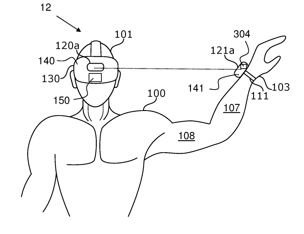
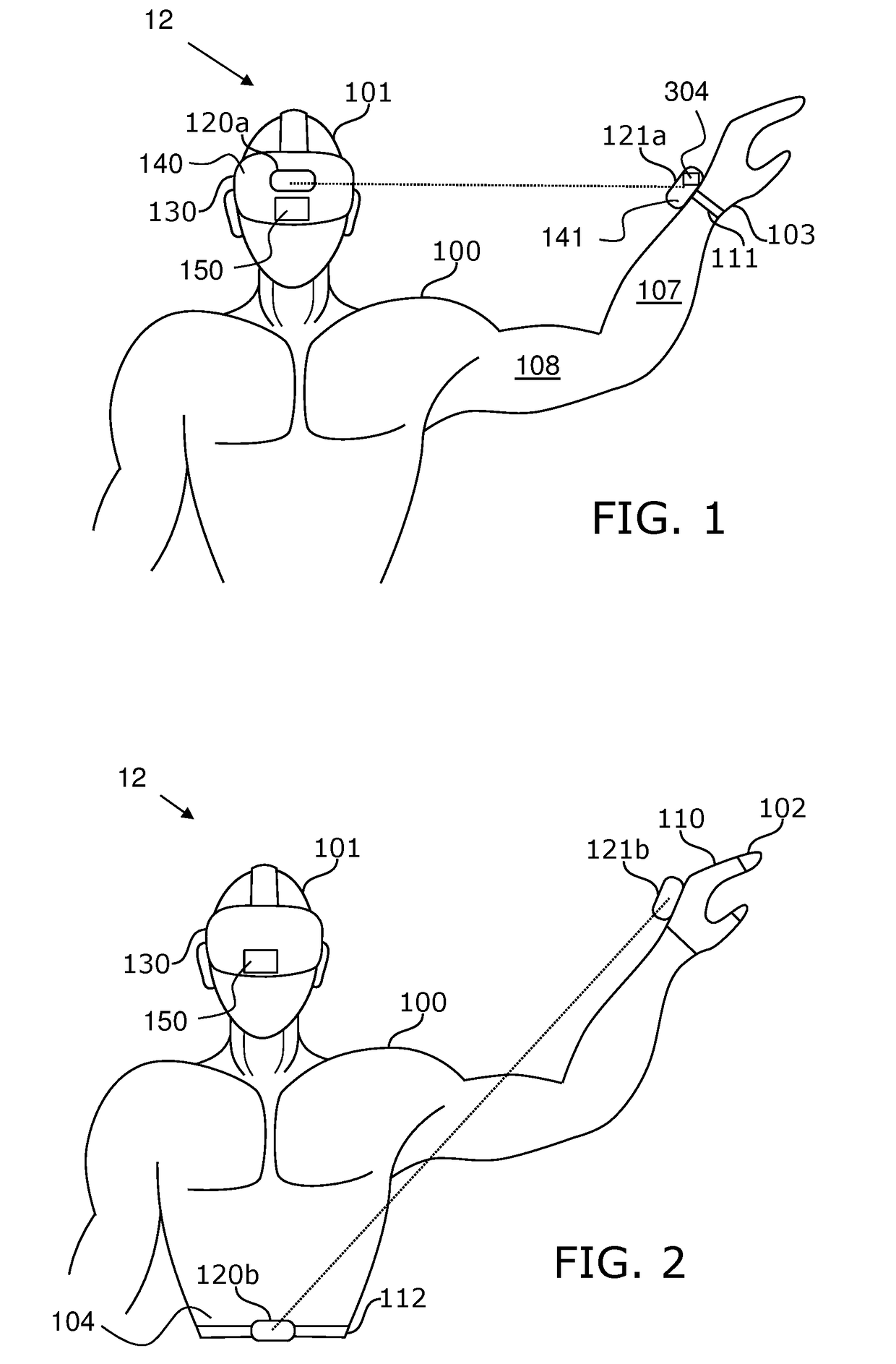
[0089]FIG. 1 shows a first embodiment of a wearable motion tracking system 12 according to invention. Said wearable motion tracking system 12 comprises a first measurement device 120a (the tracking device) that is attached to, e.g. integrated into, a head-mounted display 130 on a first body part of a user 100, the first body part being a head 101 of the user 100. The head-mounted display 130 is, in the first embodiment, a reference unit that sets the reference frame in which the tracking is done. A second measurement device 121a (the tracked device) is attached to a wristband 111 disposed on a second...


PUM


Abstract

A wearable motion tracking system (12) for capturing a relative position between a first body part (101) and a second body part (103) of said user (100) comprising a first measurement device (120a), a second measurement device (121a) and a computing device (150) that are configured such as to obtain by said computing device (150) a plurality of measurements between said first and second measurement devices (120a, 121a). Based on the plurality of measurements that comprises at least one distance measurement between said first and second measurement devices (120a, 121a) said computing device (150) is configured to compute, in three dimensions, a position of said second measurement device (121a) relative to said first measurement device (120a) for tracking the position of said second body part (103) relative to said first body part (101). The present invention further relates to a method of motion tracking.

Description

TECHNICAL FIELD[0001]The present invention relates to a wearable motion tracking system for capturing a relative position between a first body part of a user, preferably a head or a torso, and a second body part of said user, preferably a upper limb, wrist or a hand. Moreover, the present invention relates to a method for capturing the relative position between the first and second body parts for tracking the position of the second body part relative to the first body part. The resulting data may be implemented, preferably in real-time (with low latency) into a virtual environment. The present invention may be used to establish a link from a human being into a virtual environment.PRIOR ART[0002]Tracking the human body motion is used in many different applications. The filming industry captures motions to render virtual characters in movies. In sports, capturing a specific motion can give feedback about the correctness of the same. In healthcare, motion data can provide information a...

Claims


Application Information

Patent Timeline
Patent Type & Authority Applications(United States)
IPC IPC(8): G06F3/01
CPCG06F3/011G06F3/017A61B5/11
Inventor RANIERI, NICOLAWENNER, FABIANADELSBERGER, ROLFSEIFERT, HAGEN
Owner SENSORYX AG
Why Eureka
Try Eureka