Brushless can motor

a brushless, can motor technology, applied in the direction of mechanical energy handling, magnetic circuit rotating parts, magnetic circuit shape/form/construction, etc., can solve the problems of not being able to disassemble and repair motors, no motor housing, and power tools once manufactured are difficult to be repaired by the end user, etc., to achieve high torque to weight ratio, increase reliability, and more torque per watt

Active Publication Date: 2018-05-31
TTI MACAO COMML OFFSHORE LTD
View PDF5 Cites 11 Cited by
  • Summary
  • Abstract
  • Description
  • Claims
  • Application Information

AI Technical Summary

Benefits of technology

[0017]There are many advantages to the present invention. For example the brushless DC motor according to the present invention has a form factor which is the same as a traditional can motor. With the motor being in a substantial cylindrical shape, the brushless DC motor can be used to replace can motors which has similar or identical dimensions in various electrical appliances including power tools. Apparently, old electrical appliances will benefit from the advantages brought by brushless DC motors over conventional DC can motors including but not limited to high torque to weight ratio, more torque per watt, increased reliability, reduced noise, and longer lifetime. More importantly, the user does not have to invest in new electrical appliances to obtai

Problems solved by technology

Can motors are usually not designed to be disassembled and repaired.
However, most conventional brushless DC motors are made in the form of “open frame”, which means that there is no motor housing or “can” like that in can motors to enclose the brushless moto

Method used


Image

  • Brushless can motor
  • Brushless can motor
  • Brushless can motor

Examples


Embodiment Construction

[0029]In the claims which follow and in the preceding description of the invention, except where the context requires otherwise due to express language or necessary implication, the word “comprise” or variations such as “comprises” or “comprising” is used in an inclusive sense, i.e. to specify the presence of the stated features but not to preclude the presence or addition of further features in various embodiments of the invention.

[0030]As used herein and in the claims, “couple” or “connect” refers to electrical coupling or connection either directly or indirectly via one or more electrical means unless otherwise stated.

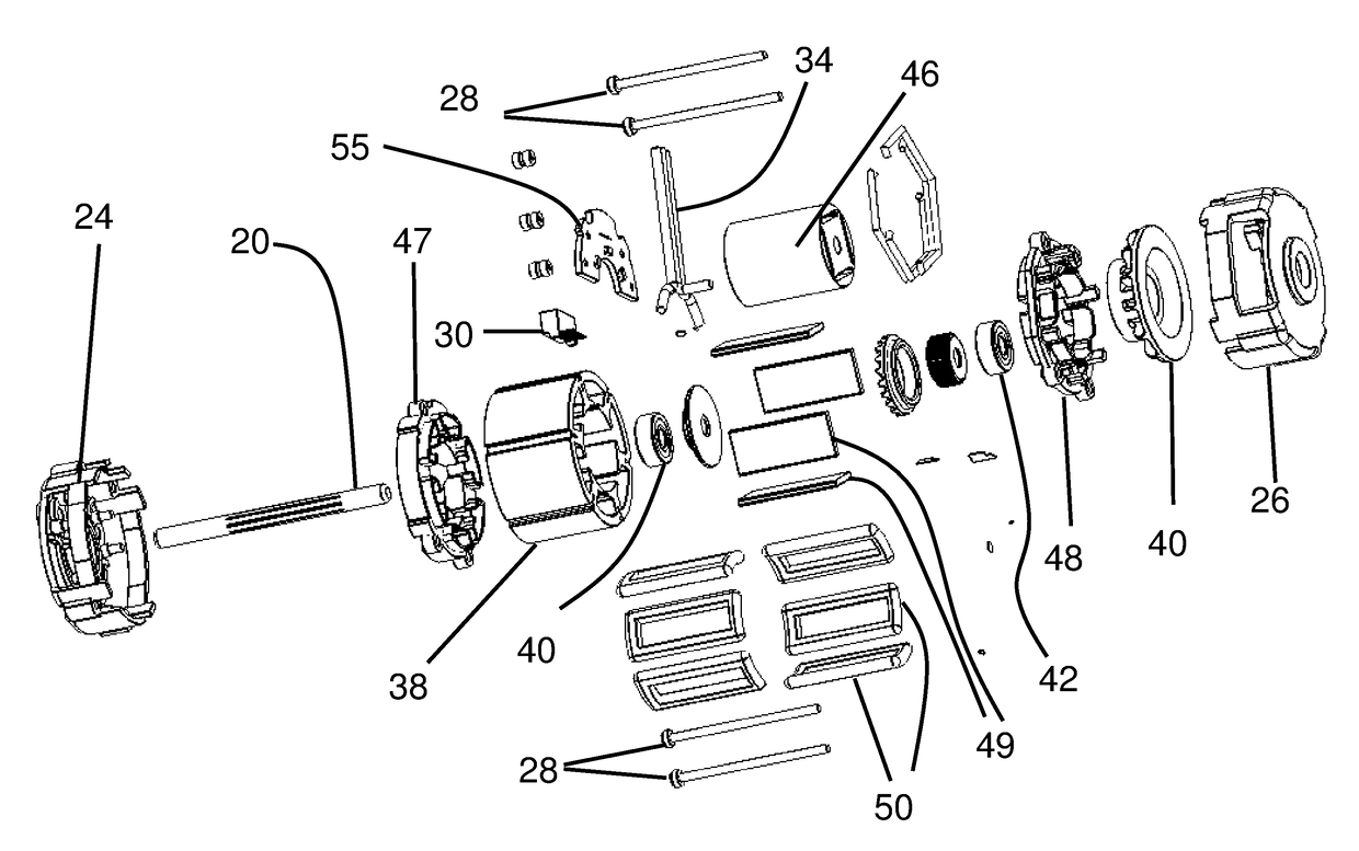
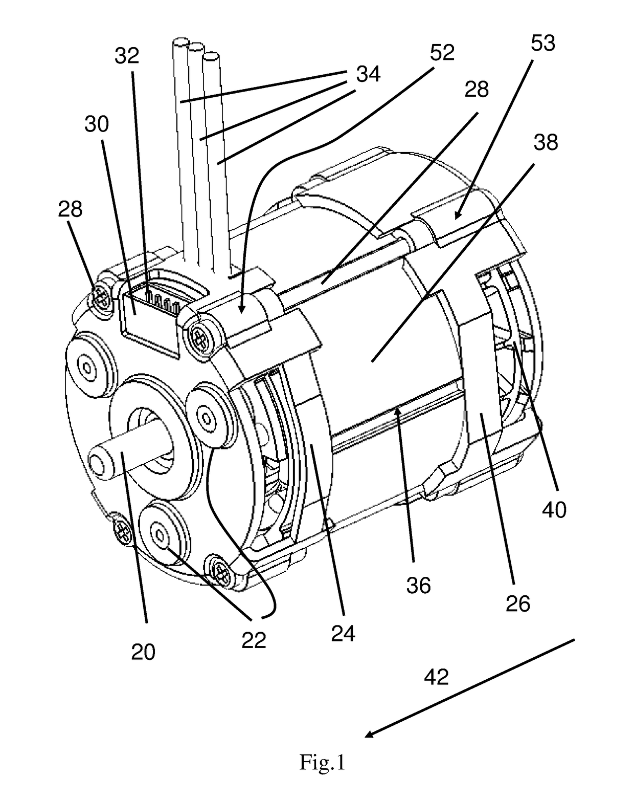
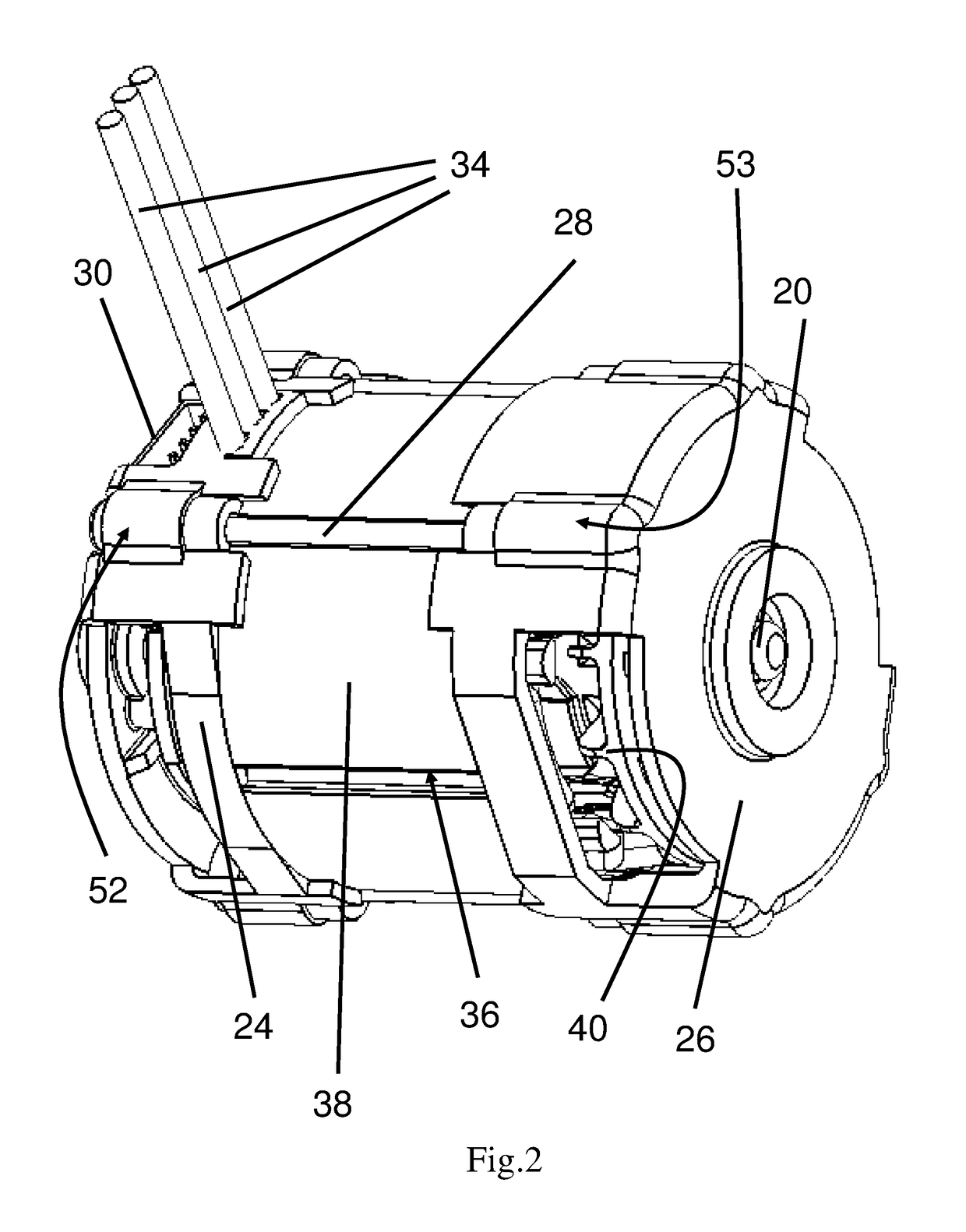
[0031]Referring now to FIGS. 1 and 2, the first embodiment of the present invention is a brushless DC motor which has a substantially cylindrical can shape. The brushless can motor in FIG. 1 includes a motor shaft 20, a first end cap 24, a stator 38, and a second end cap 26, all of which are arranged concentrically along the axis defined by the motor shaft 20. The m...


PUM


Abstract

A brushless can motor includes a motor shaft, a rotor fixed to the motor shaft, a first end cap on which a first end of the motor shaft is rotatably supported, a second end cap on which a second end of the motor shaft is rotatably supported, and a stator placed between the first end cap and the second end cap along a longitudinal direction of the brushless motor. The rotor includes a plurality of magnets. The stator is configured with a plurality of windings adapted to connect to an external motor controller. The first end cap, the second end cap, and the stator are all formed in substantially cylindrical shape, such that said brushless motor, in its assembled form, has a substantially can shape.

Description

FIELD OF INVENTION[0001]This invention relates to electrical motors, and in particular to the structure of brushless direct current (DC) motors.BACKGROUND OF INVENTION[0002]In the field of power tools, and specifically in the field of battery-powered hand tools such as drills, one common type of motors used to provide the driving force is a self-contained “can-type” or “can” motor. They are permanent magnet DC motors and usually come with the armature wound on an iron core. Can motors typically include a housing in the form of a cylindrical can in which essentially all of the components of the motor are received, including the armature, magnets, brushes, motor housing, fan, and bearings. Most DC battery-powered tools incorporate a can motor to drive the power tool output due to the simplicity of assembly and low cost of can motors. Can motors are usually not designed to be disassembled and repaired. Rather, when a motor in a power tool burns out or wears out it is cheap enough to si...

Claims


Application Information

Patent Timeline
IPC IPC(8): H02K1/18H02K1/16H02K1/27H02K5/22H02K7/14H02K11/215
CPCH02K1/185H02K1/16H02K1/2753H02K5/225H02K7/145H02K11/215H02K2211/03H02K29/08H02K5/04H02K5/15H02K9/06H02K3/522H02K2203/12
Inventor CHANG, YIJIAWEI, KAIMINGHE, JIANWEIQIAN, ZHICUN
Owner TTI MACAO COMML OFFSHORE LTD
Why Eureka
Try Eureka