Crop Machine with an Electronically Controlled Hydraulic Cylinder Flotation System

a technology of hydraulic cylinder and flotation system, which is applied in agricultural machines, applications, servomotors, etc., can solve the problems of undesirable higher ground pressure, poor ground following capability, and significant wear on the ground contacting components, so as to improve the response to forces, improve the effect of response to force, and reduce the effect of lifting action

Active Publication Date: 2018-06-07
MACDON INDS
View PDF30 Cites 17 Cited by
  • Summary
  • Abstract
  • Description
  • Claims
  • Application Information

AI Technical Summary

Benefits of technology

[0066]the electronic control system being arranged to vary the pressure such that the lifting force from the support apparatus is reduced both when the crop component floats upwardly from said intermediate float position and when the crop component floats downwardly from said intermediate float position.
[0137]-a- Oscillating float pressure to reduce effects of proportional PRR valve hysteresis as well as system (mechanical) and cylinder seal friction.

Problems solved by technology

However, due to internal friction of the cylinder seals of the flotation cylinders, these systems typically have poor ground following capabilities unless the mass supported by the ground is significant, in the order of 15% of the header mass.
With this level of ground pressure (mass of header carried by the ground), wear on the ground contacting components is significant.
Also, when hitting an obstacle, a higher ground pressure is undesirable.
If the header falls too slowly, regions of the field may not be cut at the desired height.
If the header falls too rapidly, however, the header may impact or ride roughly over the ground, thereby resulting in undesirably harsh or jarring ride characteristics.
It is also possible that the header could impact the ground in some conditions, such as uneven terrain, with sufficient force to result in damage to the header and / or the crop.

Method used


Image

  • Crop Machine with an Electronically Controlled Hydraulic Cylinder Flotation System
  • Crop Machine with an Electronically Controlled Hydraulic Cylinder Flotation System
  • Crop Machine with an Electronically Controlled Hydraulic Cylinder Flotation System

Examples


Embodiment Construction

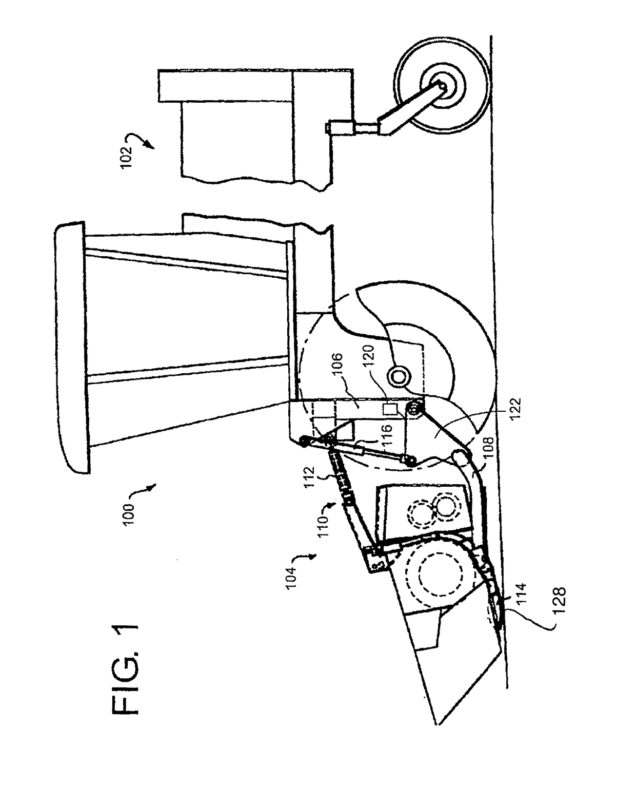
[0169]FIG. 1 shows the present invention utilized in connection with the self-propelled windrower 100, however, it will be appreciated that the principles of the present invention are not limited to a self-propelled windrower, or to any specific in type of harvesting machine having a header. The figure shows windrower 100, which comprises a tractor 102 and a header 104. The header 104 is pivotally attached to the front end of the frame or chassis 106 of windrower 100 such that it can move up and down with respect to chassis 106.

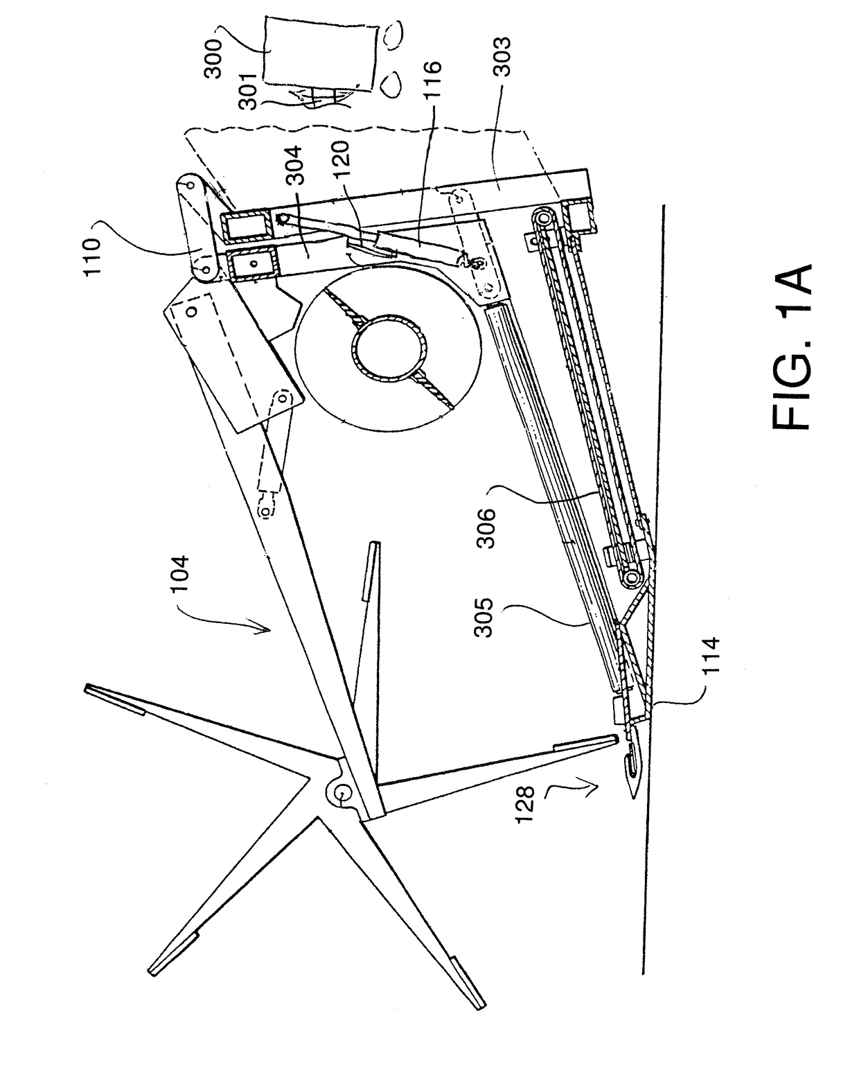
[0170]Such attachment of the header 104 to the frame 106 is achieved through a pair of lower arms 108 (only the left one being shown, the right one being in the same position and in mirror configuration on the right side of the vehicle) pivoted at one end to the frame 106 and at the other end to the header 104 as well as through a central upper link 110.

[0171]The link 110 may take the form of a single or double hydraulic cylinder 112 whose extension and retra...


PUM


Abstract

A header is supported by a pair of hydraulic float cylinders, where a float pressure to the cylinders is directly controlled by an electronic control supplying a variable control signal to a PPRR valve arrangement to maintain the float pressure at a predetermined value. At the set pressure a predetermined lifting force is provided to the header. A position sensor is used to generate an indication of movement and / or acceleration and / or velocity. The electronic control is arranged, in response to changes in the sensor signal, to temporarily change the control signal to vary the lifting force and thus change the dynamic response of the hydraulic float cylinder. A lift force greater than that required to lift the header can be provided by a lift cylinder and can be opposed in a controlled manner to apply a controlled downforce by the back of the same cylinder or by a separate component.

Description

[0001]This application is a continuation in part application of application Ser. No. 15 / 188,468 filed Jun. 21, 2016.[0002]This invention relates to crop machine with an electronically controlled hydraulic cylinder flotation system of the header on support tractor. In particular the arrangement provides firstly a construction in which the effect of static friction provided by cylinder seals is significantly reduced so as to reduce resistance to motion of the cylinder in the floating action. Secondly the arrangement herein provides a dynamic control system which modifies the forces applied by the cylinder in response to movement of the header relative to the tractor. The present invention can be used in many different engaging systems such as hay tools, rakes, pickups, etc but is particularly applicable both for swathers or windrowers where the header is carried on a swather tractor and for combine harvesters where the header is carried by a combine adapter connected to the feeder hou...

Claims


Application Information

Patent Timeline
Patent Type & Authority Applications(United States)
IPC IPC(8): A01D41/14A01B63/00A01B63/108A01D41/127
CPCA01D41/141A01B63/008A01B63/108A01D41/127A01D41/1243F15B11/08F15B13/044F15B2211/7051F15B1/024F15B11/10F15B21/14F15B2211/20546F15B2211/30565F15B2211/3059F15B2211/5151F15B2211/526F15B2211/625F15B2211/6309F15B2211/6313F15B2211/6336F15B2211/6653F15B2211/7128F15B2211/761
Inventor DUNN, JAMES THOMASLEVERICK, GRAHAM MICHAELLYONS, RUSSELL GEORGESHEARER, BRUCE ROBERTBOCH, KYLE EDWARD
Owner MACDON INDS
Why Eureka
Try Eureka