Optical sensor device, sensor apparatus, cable and method of manufacturing

a sensor and optical sensor technology, applied in the field of optical sensor devices, can solve the problems of manufacturing, performance and handling problems, the minimum achievable diameter of glass fibers including an fbg is limited, and the minimum stiffness sets a limit to the obtainable sensitivity, and achieves the effect of stable deflection position

Active Publication Date: 2018-06-07
OPTICS11 BV +1
View PDF0 Cites 3 Cited by
  • Summary
  • Abstract
  • Description
  • Claims
  • Application Information

AI Technical Summary

Benefits of technology

[0019]In accordance with some further embodiments, the bi-stable spring comprises a deflection element and one or more leaf springs, the leaf springs connecting the deflection element with a fixed element, wherein the fixed element is fixed with respect to the reference body. The one or more leaf springs connect the deflection element to the fixed element in such a manner as to provide the deflection element with the first and a second stable deflection position. Such a bi-stable spring allows compact installation in an optical sensor device that may be made small in size. In some embodiments, the leaf springs of the bi-stable spring are buckled by pre-stressing these during manufacturing.
[0020]In some particular embodiments, the one or more leaf springs extend from fixed element under an angle therewith in a direction towards one of the first and second stable deflection p

Problems solved by technology

For example, there is a limitation in minimum achievable diameter for glass fibers including an FBG.
Beyond the minimum diameter achievable (i.e. at even smaller diameters), manufacturing, pe

Method used


Image

  • Optical sensor device, sensor apparatus, cable and method of manufacturing
  • Optical sensor device, sensor apparatus, cable and method of manufacturing
  • Optical sensor device, sensor apparatus, cable and method of manufacturing

Examples


Embodiment Construction

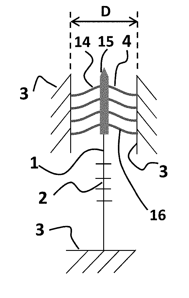
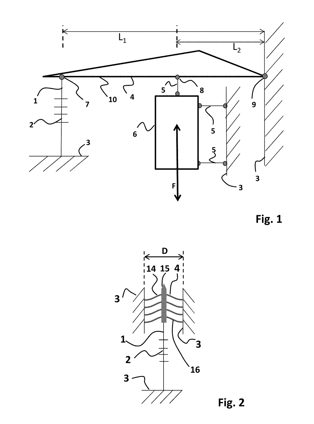
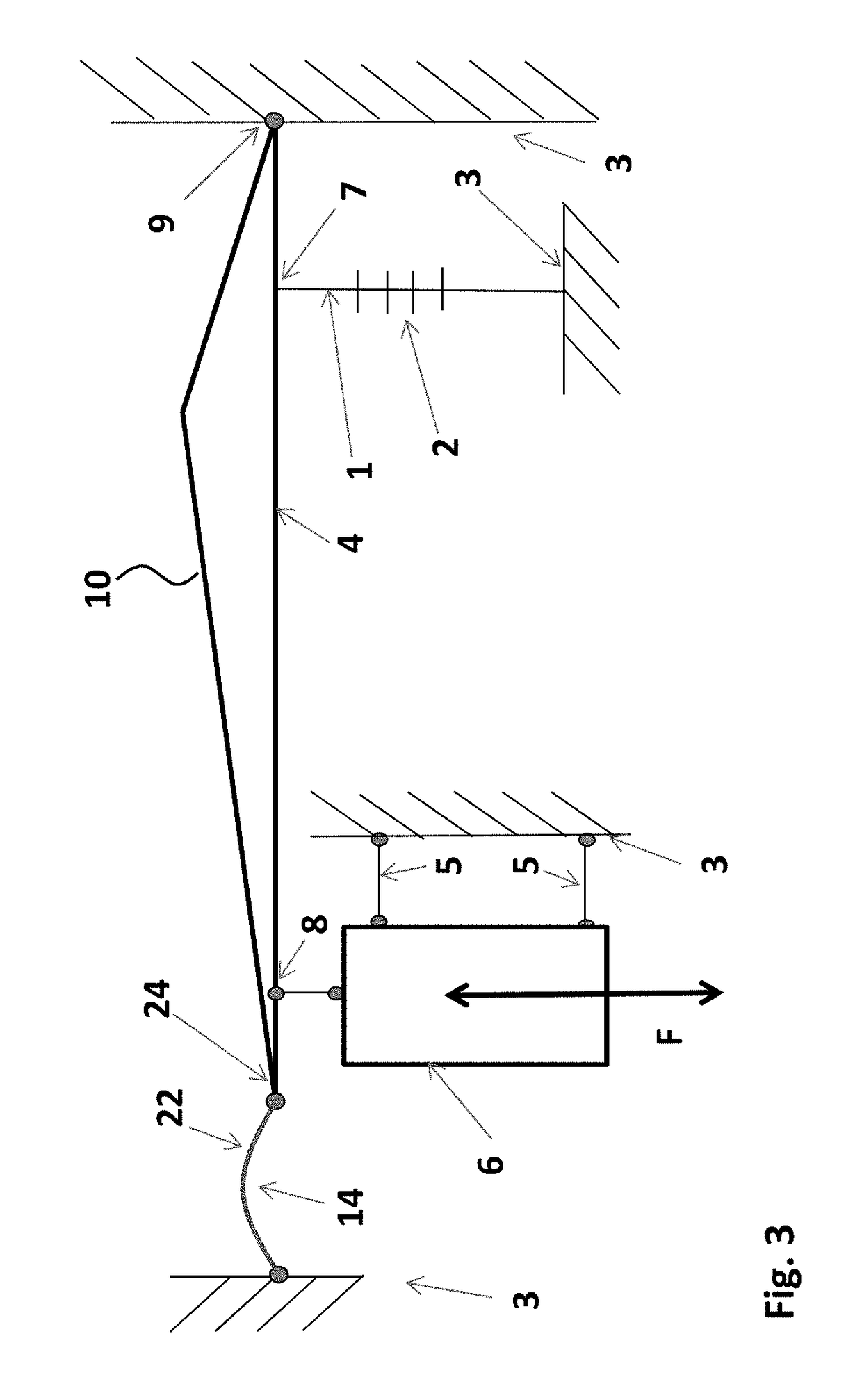
[0037]The advantages of the optical sensor device of present invention may become more clear by considering the sensitivity of an optical accelerometer. In the exemplary accelerometer of FIG. 1, a sensing element 6 is formed by an inertial mass. The sensing element 6 is arranged for receiving an input action F, e.g. a vibration as is schematically indicated by the double arrow. The sensing element 6 is connected to a fixed reference body 3 by means of hingeable connections 5, and further to a transmission arm 10 by a further hingeable connection 5 at location 8 along the arm 10. The transmission arm 10 is part of transmission structure 4, and is connected by a pivot 9 to the fixed reference body 3. Moreover, at location 7 along the transmission arm 10, an optical fiber 1 comprising a fiber bragg grating (FBG) 2 is connected thereto. The optical fiber 1 comprising the FBG 2 is further connected to the fixed reference body 3 on its other end with respect to the FBG 2. As may be apprec...


PUM


Abstract

The invention is directed at an optical sensor device, comprising a sensing element for receiving an input action, an optical fiber comprising an intrinsic fiber optic sensor, and a transmission structure arranged for exerting a sensing action on the optical fiber in response to the input action received by the sensing element, wherein the optical fiber in a first connecting part thereof is connected to a reference body and wherein the optical fiber in a second connecting part thereof is to the transmission structure for receiving the sensing action, the first connecting part and the second connecting part of the optical fiber being located on either side of the intrinsic fiber optic sensor, wherein the transmission structure comprises a bi-stable spring having a first and a second stable deflection position and a negative stiffness range around an unstable equilibrium position between the first and second stable deflection position, and wherein the optical fiber between the transmission structure and the reference body is pre-stressed such as to be tensed, said optical fiber thereby acting as a spring having a first spring constant of positive value, wherein the optical fiber thereby counteracts a spring action of the bi-stable spring such as to operate the bi-stable spring in a deflection position range within the negative stiffness range, the deflection position range not including the unstable equilibrium position of the bi-stable spring.

Description

FIELD OF THE INVENTION[0001]The present invention relates to an optical sensor device, in particular an optical sensor device applying an intrinsic fiber optic sensor. The invention further relates to a method of manufacturing.BACKGROUND[0002]A known class of optical sensors for various applications includes the use of intrinsic fiber optic sensors. An intrinsic fiber optic sensor is a sensor that uses an optical fiber as sensing element. In many applications the intrinsic fiber optic sensor is lit (e.g. by a laser), and a change in the fiber due to an external cause (dependent on the type of sensor) results in a measurable change in the optical signal transmitted by or received from the sensor. A typical example of an intrinsic fiber optic sensor is a Fiber Bragg Grating (FBG).[0003]An FBG comprises a fiber having a core including therein, over a certain distance, a periodic variation of the refractive index. This periodic variation forms a wavelength-specific dielectric mirror, wh...

Claims


Application Information

Patent Timeline
IPC IPC(8): G01D5/353G01L1/24G01H9/00G01P15/093
CPCG01D5/35377G01D5/35316G01L1/246G01H9/004G01P15/093G01P2015/0857G01L5/0057G01P2015/0837
Inventor KNOPPERS, GERMAN ENRIQUEWAGEMAKERS, THOMAS THEODORUS NICOLAAS JOHANNESKARABACAK, DEVREZ MEHMETVAN BEELEN, RUDOLF KLAASMEULBLOK, BASTIAAN
Owner OPTICS11 BV
Why Eureka
Try Eureka