Microscope for molecular spectroscopic analysis

a molecular spectroscopic and microscope technology, applied in the direction of instruments, spectrometry/spectrophotometry/monochromators, optical radiation measurement, etc., can solve the problems of difficult to distinguish diseases simply on the basis of their symptoms, difficult to make clear and reliable statements, and relatively time-consuming

Active Publication Date: 2018-06-07
BADEN WURTTEMBERG STIFFUNG GMBH
View PDF0 Cites 2 Cited by
  • Summary
  • Abstract
  • Description
  • Claims
  • Application Information

AI Technical Summary

Problems solved by technology

A distinction between diseases simply on the basis of the symptoms thereof is often impossible because different diseases result in similar, partially overlapping symptoms although they can be attributed to different medical causes.
However, the meaningfulness of fine sections dyed in this manner is substantially dependent on the interaction of the tissue with the dyes so that clear and reliable statements are often made more difficult by imperfect dyeing.
Furthermore, this procedure is connected with a relatively large number of operating steps and is therefore relatively time-consuming.
However, the conventional FTIR mapping is extremely time-consuming as a result of the point for point mapping.
Although the method can be accelerated as a result of the parallel recording of a plurality of spectrums, the sensors (FPA) necessary for this purpose are extremely expensive.
However, reliable results could also previously be achieved with these devices only by using cost-intensive semiconductor detectors (for example, mercury / cadmium / tellurite (MCT) FPA) so that a substantial advantage over conventional FTIR technology has not been afforded in this regard.

Method used


Image

  • Microscope for molecular spectroscopic analysis
  • Microscope for molecular spectroscopic analysis
  • Microscope for molecular spectroscopic analysis

Examples


examples

1. Preferred Embodiments

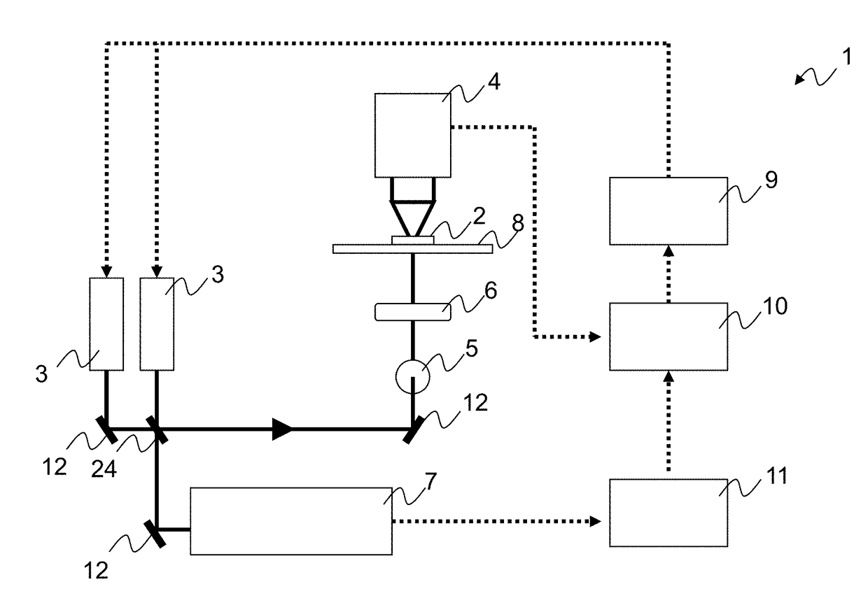
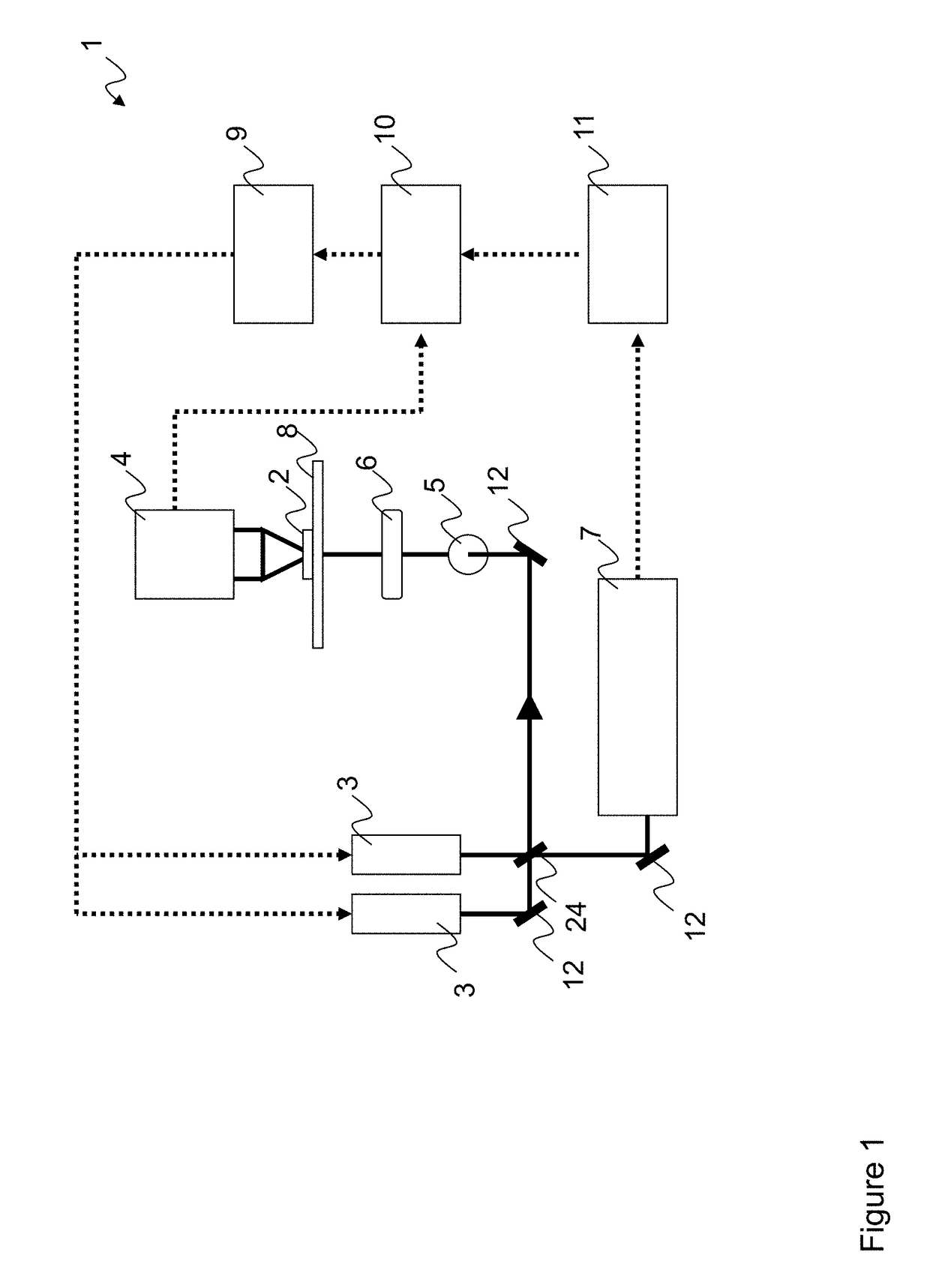
[0093]FIG. 1 shows a first general embodiment of the microscope 1 according to the invention. The microscope 1 comprises two QCLs 3, the laser beams of which are emitted via redirecting mirrors 12 and beam splitters 24 onto a rotating phase modulator 5. Subsequently, the radiation falls through a lens 6 onto a sample 2, which is fixed to a sample holder 8. The IR radiation which is emitted by the sample 2 is detected by a sensor 4. At the same time, a portion of the laser radiation of the QCLs 3 is supplied to a wavelength referencing 7 via a beam splitter 24. The control and verification of the microscope 1 are brought about via a laser control 9, a recording unit 10 and a lock-in amplifier 11.

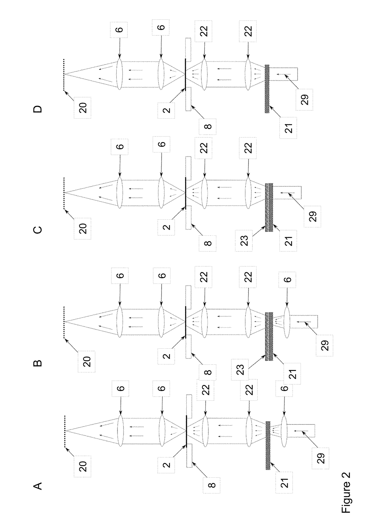
[0094]FIG. 2 shows embodiments of the beam path through the microscope 1 during transmission (FIGS. 2 A to D, I and J) and reflection (FIGS. 2 E to H, K and L), wherein the IR radiation is imaged directly onto the sample. Both a rotating IR-transparent scattering plate...


PUM


Abstract

The invention relates to a microscope for the molecular spectroscopic analysis of a sample (2), having a beam path having at least one quantum cascade laser (QCL) (3) which emits an infrared (IR) radiation, a phase modulator (5) which is arranged between the QCL (3) and the sample (2), at least one optical element (6) which is arranged between the phase modulator (5) and the sample (2) and a sensor (4) which detects an IR radiation which is transmitted and/or reflected by the sample (2). The invention relates further to a method for the molecular spectroscopic analysis of a sample (2) comprising the steps of irradiating the sample (2) with an infrared (IR) radiation by means of a quantum cascade laser (QCL) (3), wherein the IR radiation is directed onto the sample (2) via a phase modulator (5) and at least one optical element (6), and detecting the IR radiation which is reflected and/or transmitted by the sample (2).

Description

FIELD OF THE INVENTION[0001]The invention relates to a microscope for the molecular spectroscopic analysis of a sample, having a beam path having at least one quantum cascade laser (QCL) which emits an infrared (IR) radiation, a phase modulator which is arranged between the QCL and the sample, at least one optical element which is arranged between the phase modulator and the sample and a sensor which detects an IR radiation which is transmitted and / or reflected by the sample. The invention further relates to a method for the molecular spectroscopic analysis of a sample comprising the steps of irradiating the sample with an infrared (IR) radiation by means of a quantum cascade laser (QCL), wherein the IR radiation is directed onto the sample via a phase modulator and at least one optical element, and detecting the IR radiation which is reflected and / or transmitted by the sample.BACKGROUND OF THE INVENTION[0002]In order to treat diseases in an advantageous and successful manner, a rel...

Claims


Application Information

Patent Timeline
Patent Type & Authority Applications(United States)
IPC IPC(8): G02B21/00G01J3/02G01J3/28G01J3/42G02B21/06G02B21/36
CPCG02B21/0004G01J3/0205G01J3/2803G01J3/42G02B21/0096G02B21/06G02B21/361G01J2003/423G01N21/35
Inventor KROEGER-LUI, NIELS
Owner BADEN WURTTEMBERG STIFFUNG GMBH
Why Eureka
Try Eureka