
Wireless power transmission device

a power transmission device and wireless technology, applied in the direction of electrical equipment, transformers, inductances, etc., can solve the problems of instantaneous discharge phenomenon and deterioration of appearance, and achieve the effect of stably transmitting and minimizing volume and unit cos

Active Publication Date: 2018-06-07
GE HYBRID TECH
View PDF4 Cites 11 Cited by
  • Summary
  • Abstract
  • Description
  • Claims
  • Application Information

AI Technical Summary

Benefits of technology

The patent text describes a way to transmit wireless power using a resonant coil that has a constant quality factor (Q-factor) to ensure stable power transmission. The text also suggests using two kinds of coils that have both induction and resonance functions to minimize volume and cost. Additionally, the text explains how to independently implement induction-based and resonance-based wireless charging by mounting a switch function onto a coil with resonance function.

Problems solved by technology

Accordingly, when much equipment of terminal supply method is used, many cables occupy a considerable work space, and are difficult to arrange, thereby deteriorating the appearance.
Also, the terminal supply method may cause limitations such as an instantaneous discharge phenomenon due to potential differences between terminals, a burnout and fire due to sticking of foreign objects, a natural discharge, a lifespan and performance reduction of a battery pack and the like.

Method used


Image

  • Wireless power transmission device
  • Wireless power transmission device
  • Wireless power transmission device

Examples


Embodiment Construction

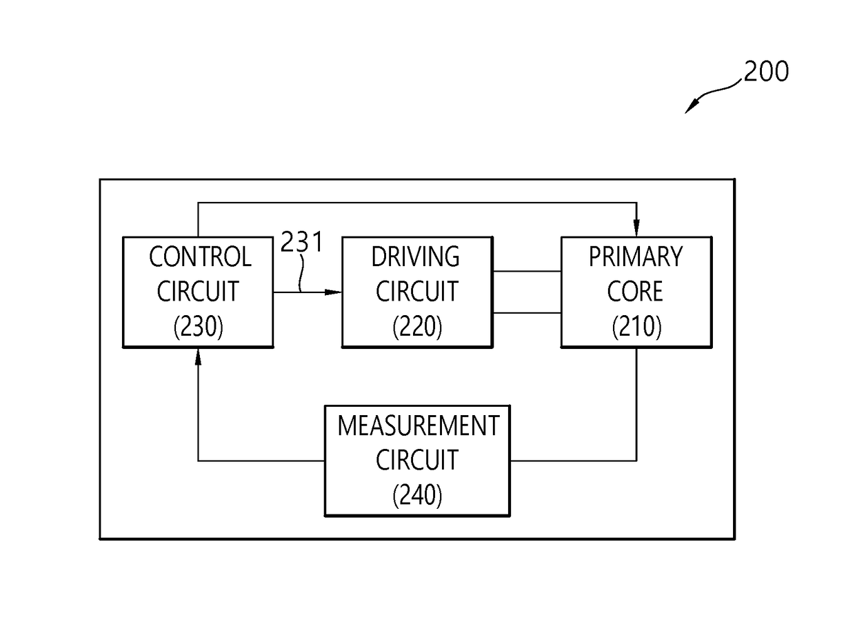
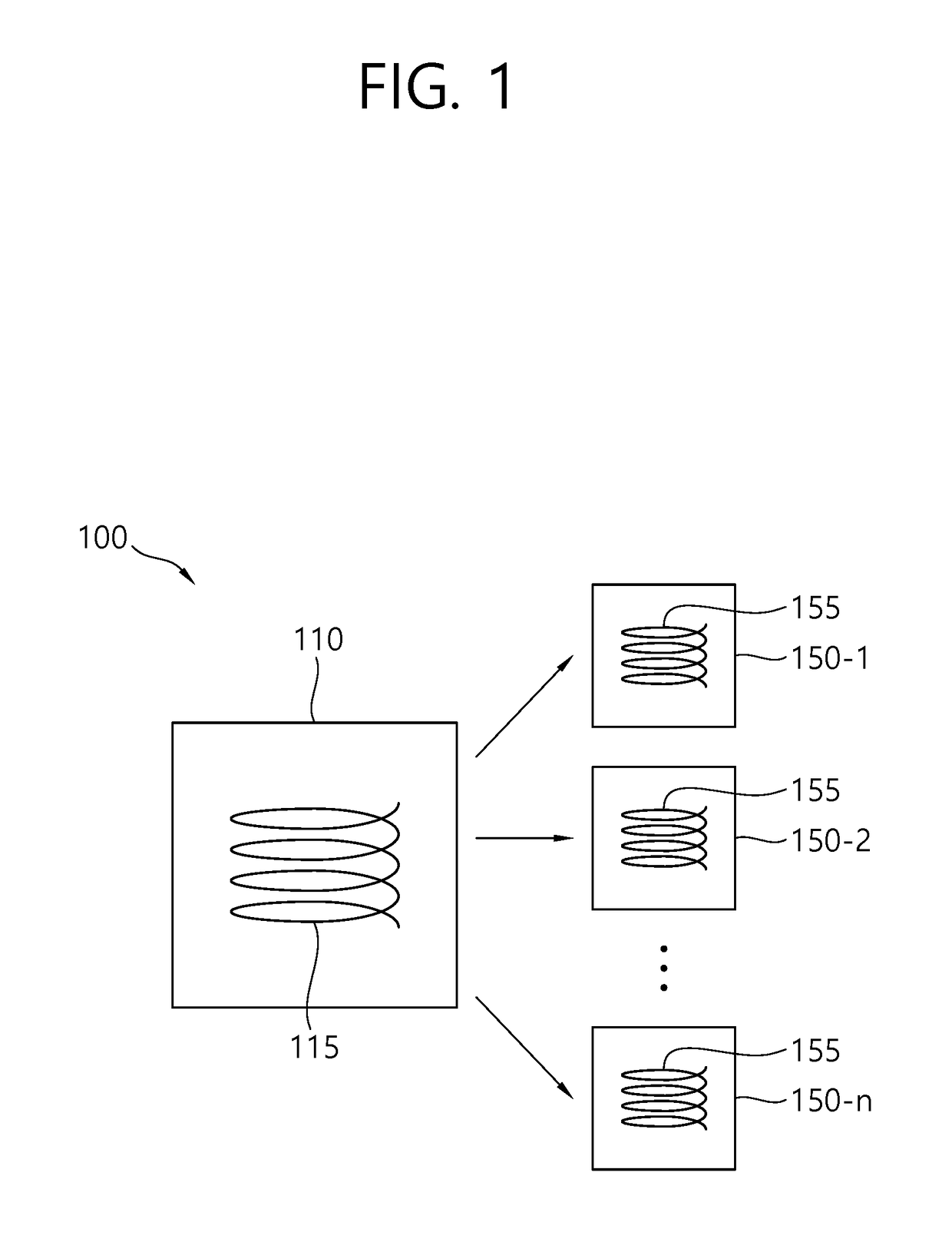
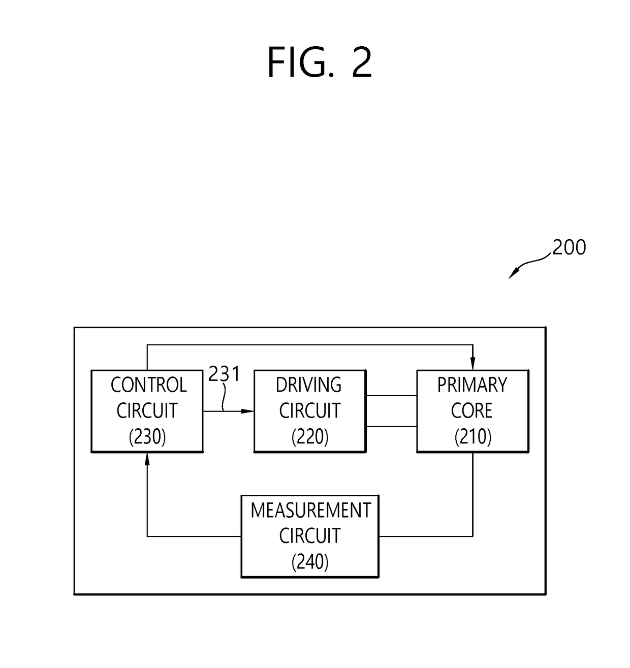
[0035]The term ‘wireless power’ below is used to mean any type of energy associated with an electric field, a magnetic field, and an electromagnetic field transmitted from a wireless power transmission apparatus to a wireless power reception apparatus without the use of physical electromagnetic conductors. The wireless power may also be referred to as a power signal or wireless energy, and may denote an oscillating magnetic flux enclosed by the primary and secondary coils. For example, power conversion in a system to wirelessly charge devices including mobile phones, cordless phones, iPods, MP3 players, headsets and the like will be described herein. In this disclosure, the basic principles of wireless power transmission include, for example, both magnetic induction coupling and magnetic resonance coupling that uses frequencies of less than 30 MHz. However, various frequencies at which license-exempt operations at relatively high radiation levels, for example, less than 135 kHz (LF)...


PUM

PropertyMeasurementUnit
frequenciesaaaaaaaaaa

Abstract

A coil structure for wireless power transmission is provided. The coil structure comprises: a primary resonance coil wound in a spiral shape around a centripetal point; a primary induction coil, which supplies power to the primary resonance coil in a nonconnected state with an input or output terminal of the primary resonance coil and is wound in a spiral shape on a substantially same plane around a substantially same centripetal point as the centripetal point; a switch configured to be parallel with the primary resonance coil so as to control the ON and OFF of an operation of the primary resonance coil; and a capacitor coupled to the primary resonance coil so as to form a magnetic resonance with the primary resonance coil.

Description

BACKGROUND OF THE INVENTIONField of the Invention[0001]The present invention relates to wireless power, and more particularly, to a wireless power transmission apparatus and a coil structure for implementing the wireless power transmission apparatus.Related Art[0002]Generally, in order for a portable terminal such as a mobile phone, a notebook, and a PDA to be charged, the portable terminal needs to receive electric energy (or electric power) from an external charger. The portable terminal includes a battery cell for storing electric energy that supplied and a circuit for charging and discharging (supplying electric energy to the portable terminal) of the battery cell.[0003]Electrical connection methods between a battery cell and a charger for charging the battery cell with electrical energy include a terminal supply method in which commercial power is supplied and converted into a voltage and a current corresponding to the battery cell and electrical energy is supplied to the batte...

Claims


Application Information

Patent Timeline
Patent Type & Authority Applications(United States)
IPC IPC(8): H02J50/12H01F38/14
CPCH02J50/12H01F38/14H02J7/025H02J50/40
Inventor JUNG, CHUN KILKIM, HAK DONOH, SANG YOUN
Owner GE HYBRID TECH
Learn More