
High-efficiency frequency doubler with a compensated transformer-based input balun

Active Publication Date: 2018-06-07
CALIFORNIA INST OF TECH +1
View PDF0 Cites 13 Cited by
  • Summary
  • Abstract
  • Description
  • Claims
  • Application Information

AI Technical Summary

Benefits of technology

This patent describes a way to take a differential input signal and turn it into a single-ended output signal. The process doubles the frequency of the input signal by canceling out a common frequency and extracting a second-order harmonic. This results in a higher-quality output signal with a better signal-to-noise ratio.

Problems solved by technology

A fundamental challenge in building such millimeter wave systems is to provide a high-speed frequency generator, such as voltage-controlled oscillator, with a wide tuning range and acceptable phase noise.
However, existing frequency multipliers generally do not operate well at extremely high frequencies above 60 GHz.
Also, most frequency multiplier designs can only operate within a limited operating frequency range, thus being unsuitable for applications, such as 5G wireless systems, which require a wide range of operating frequencies.

Method used


Image

  • High-efficiency frequency doubler with a compensated transformer-based input balun
  • High-efficiency frequency doubler with a compensated transformer-based input balun
  • High-efficiency frequency doubler with a compensated transformer-based input balun

Examples


Embodiment Construction

[0029]The following description is presented to enable any person skilled in the art to make and use the present embodiments, and is provided in the context of a particular application and its requirements. Various modifications to the disclosed embodiments will be readily apparent to those skilled in the art, and the general principles defined herein may be applied to other embodiments and applications without departing from the spirit and scope of the present embodiments. Thus, the present embodiments are not limited to the embodiments shown, but are to be accorded the widest scope consistent with the principles and features disclosed herein.

[0030]The data structures and code described in this detailed description are typically stored on a computer-readable storage medium, which may be any device or medium that can store code and / or data for use by a computer system. The computer-readable storage medium includes, but is not limited to, volatile memory, non-volatile memory, magneti...


PUM


Abstract

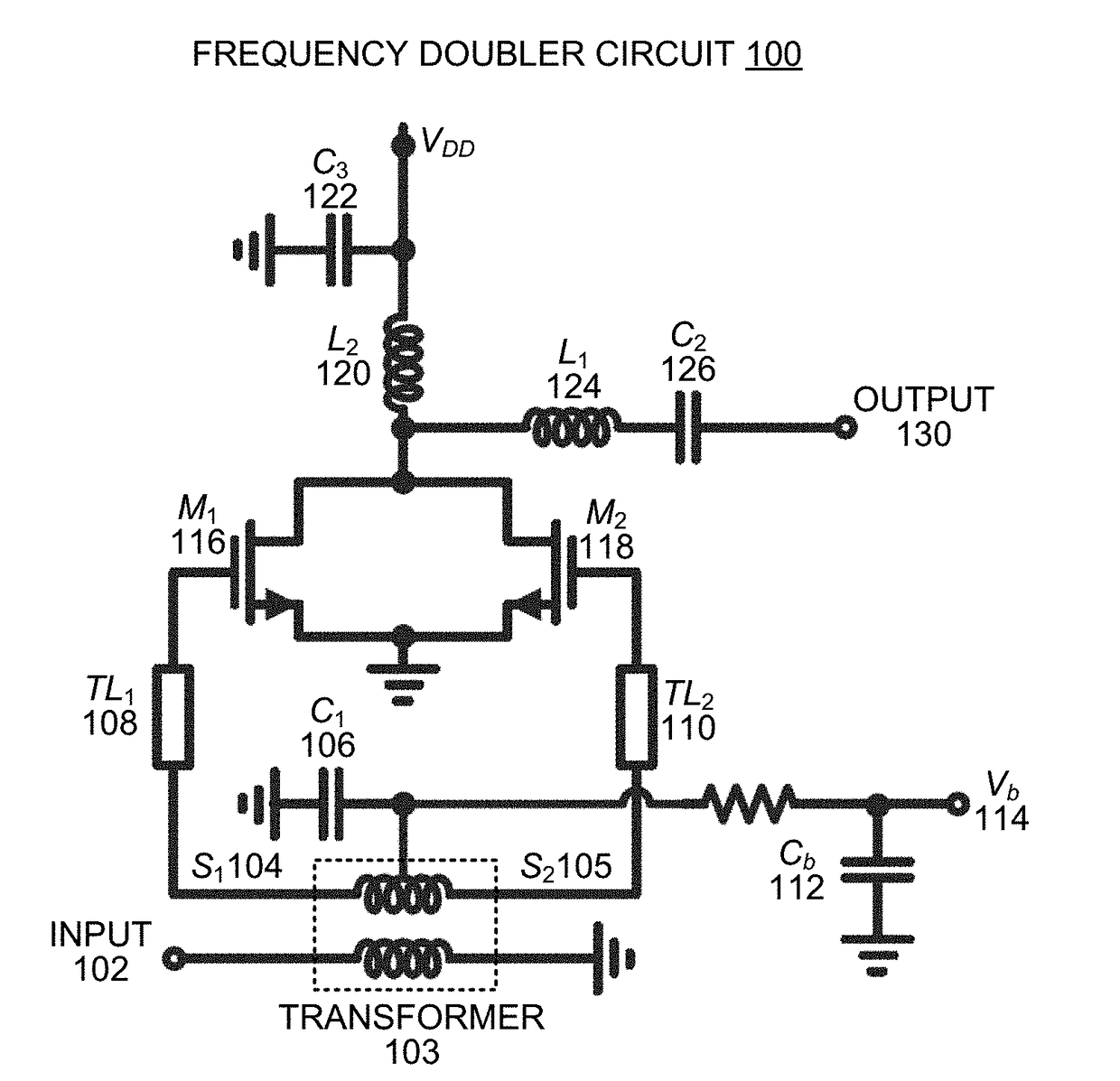
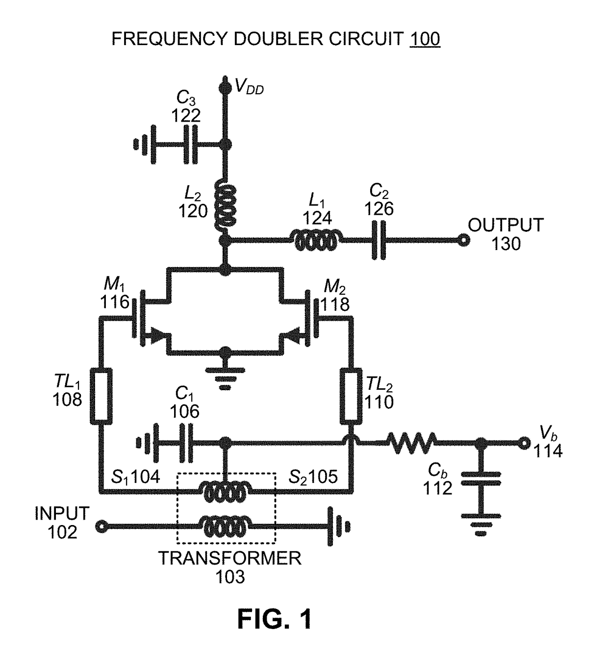
The disclosed embodiments relate to the design of a high-speed frequency doubler circuit. During operation, the circuit uses a transformer-based balun to convert a single-ended input signal into a differential signal, wherein the transformer-based balun includes a transformer with a primary coil, which receives the single-ended input signal, and a secondary coil, which produces the differential signal. The transformer also includes a central compensation capacitor coupled between a center tap of the secondary coil and ground, wherein the central compensation capacitor acts to suppress common-mode components in the differential signal. Next, the circuit uses a pseudo-differential amplifier to convert the differential signal into a single-ended output signal, which has double the frequency of the single-ended input signal.

Description

CROSS-REFERENCE TO RELATED APPLICATION[0001]This application claims the benefit of U.S. Provisional Patent Application Ser. No. 62 / 430,109, entitled “Broadband High Frequency Doubler with a Compensated Transformer-Based Balun,” by inventors Yu Ye, Arian J. Tang, Qun Gu and Brian J. Drouin, Attorney Docket Number UC15-764-1PSP, filed on 5 Dec. 2016, the contents of which are incorporated by reference herein.GOVERNMENT LICENSE RIGHTS[0002]This invention was made with U.S. government support in the performance of work under NASA contract NNN12AA01C, and is subject to the provisions of Public Law 96-517 (35 USC 202) in which the Contractor has elected to retain title. The U.S. government has certain rights in the invention.BACKGROUNDField[0003]The disclosed embodiments generally relate to the design of a frequency doubler circuit. More specifically, the disclosed embodiments relate to the design of a frequency doubler circuit having a transformer-based input balun that uses a central co...

Claims


Application Information

Patent Timeline
IPC IPC(8): H03K5/00H03H11/32H03H11/30
CPCH03K5/00006H03H11/32H03H11/30H03B19/14H03H7/42H03B2200/009
Inventor YE, YUTANG, ADRIAN J.GU, QUNDROUIN, BRIAN J.
Owner CALIFORNIA INST OF TECH
Learn More