Method for separating blood plasma and metering thereof

a technology of microfluidic devices and blood plasma, which is applied in the field of microfluidic devices for liquids, can solve the problems of time-consuming and costly steps in clinical practice, and achieve the effect of vastly reducing the time-consuming and costly steps

Active Publication Date: 2018-06-28
CAPITAINER AB
View PDF2 Cites 9 Cited by
  • Summary
  • Abstract
  • Description
  • Claims
  • Application Information

AI Technical Summary

Benefits of technology

[0008]In one general aspect, the invention is related to a method to separate blood plasma in which a blood separation membrane is combined with a capillary pump. Said blood separation membrane being a structure that separates blood cells and plasma. The membranes can be made from ceramics, polymers or cellulose-based materials. The capillary pump is a structure or material that provides capillary suction in order to facilitate effective plasma separation. In an embodiment of this general aspect, the membrane is applied in a geometrical arrangement that facilitates effective fluidic connection between the membrane and said capillary pump. One embodiment of this type is a geometrical structure in form of a wedge provides a high capillary force at the interesting planes between the membrane and the capillary structure. Another embodiment would include a porous material, said pores or microchannels providing high capillary force. The mentioned embodiments may include means to pinch off excess plasma from a metered plasma volume.
[0043]Thus liquid loaded with dissolved material of the membrane may be led into the capillary dead end channel to allow for liquid having less amount of dissolved material to propagate through the membrane once dissolved. Thus, e.g. the viscosity of the liquid may be maintained.
[0056]Thus one or more membranes may be formed in a simple manner in the microfluidic device.
[0059]Thus a plurality of dissolvable membranes and capillary channels may be formed in a simple manner in the device.
[0063]The microfluidic device can comprise a microfluidic channel, where said channel introduces a time delay for the liquid to propagate, dissolvable regions where said dissolvable regions introduce certain time delays, and where the device may have a singularity or a plurality of said dissolvable regions, said regions being realized by for example a thin film of a resorbing polymer material (e.g. PVA). These different regions may thus provide means for having delayed events occurring in the device enabling handling of for example excess liquid.

Problems solved by technology

However, if the centrifugation step could be eliminated while still providing an analyzable and volume-defined amount of plasma, time-consuming and costly steps in clinical practice would be vastly reduced.

Method used


Image

  • Method for separating blood plasma and metering thereof
  • Method for separating blood plasma and metering thereof
  • Method for separating blood plasma and metering thereof

Examples


Embodiment Construction

[0078]In the following, a detailed description of embodiments of the invention is disclosed.

Device Fabrication

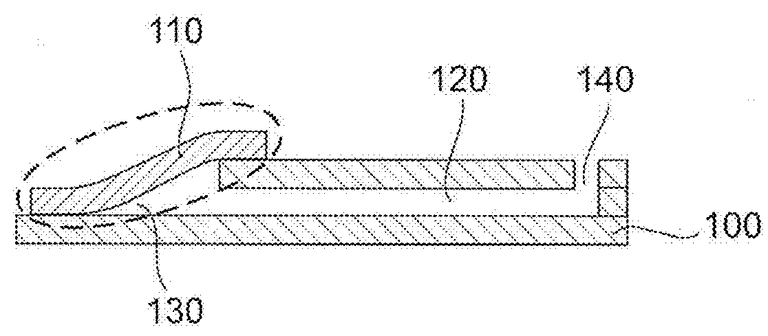
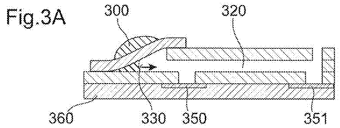
[0079]The microfluidic layer consists of hydrophilic Xerox copier transparencies (003R96002 Type C, Xerox Co. Ltd., USA) and a capillary spacer tape (IVD 090448PV1.001 / 09, Tesa GmbH, Germany). The different layers were structured separately with a cutting plotter (CE5000, Graphtec America Inc., USA) and laminated together with a laminator (H600, GBC Inc., USA). A liquid PVA solution was prepared from PVA granule (Mowiol® 4-88 Mw ˜31,000, Sigma Aldrich Inc., USA) by dissolving it in DI water and was then spin-coated onto silicon wafers and dried to form thin dissolvable films. The film thickness controlling the dissolving time was fitted to the filtration times required to fill the plasma volume in the metering channel [13]. The dissolvable films were laminated to the microfluidic layer at the openings in the bottom of the channel forming the two dissolvable valves. The micro...


PUM

PropertyMeasurementUnit
volumesaaaaaaaaaa
angleaaaaaaaaaa
angleaaaaaaaaaa

Abstract

A capillary driven microfluidic device with blood plasma separation means that can be used to separate, meter and transfer a blood sample. The blood separation means can be arranged as a capillary pump by the configuration of a porous membrane and the microfluidic device.

Description

TECHNICAL FIELD[0001]The present invention relates generally to a microfluidic device for liquids, with a capillary driven separation of blood, while generating a capillary flow of separated blood plasma.BACKGROUND OF THE INVENTION[0002]Microfluidic devices are used in a wide range of applications. Typically, a microfluidic device is defined to handle small fluid volumes (μL, nL, pL etc.), have a small size with at least one dimension in the micrometer range, and / or use effects of the microdomain. In such devices fluids may be moved, mixed, separated or otherwise processed. Numerous applications employ passive fluid control techniques like capillary forces.[0003]One important area of microfluidics is in medical devices. Microfluidic devices may be used in analytical or therapeutic applications, e.g. to administer medications or to handle samples of bodily fluids.[0004]Blood plasma based testing forms the gold standard in clinical laboratory analysis, drug development and therapeutic...

Claims


Application Information

Patent Timeline
Patent Type & Authority Applications(United States)
IPC IPC(8): B01L3/00G01N33/49G01N1/40
CPCB01L3/50273G01N33/491G01N1/4077B01L3/502753B01L3/502738G01N2001/4088B01L2200/0605B01L2200/025B01L2200/0684B01L2300/0681B01L2300/069B01L2300/126B01L2300/161B01L2400/0406B01L2400/0677B01L2300/0887B01L2300/0864B01L2400/0418B01L2400/049
Inventor ROXHED, NICLASSTEMME, GORANLENK, GABRIELVAN DER WIJNGAART, WOUTERHANSSON, JONAS
Owner CAPITAINER AB
Why Eureka
Try Eureka