Wheeled jumping robot

a robot and wheel technology, applied in the field of wheeled jumping robots, can solve the problems of restricted movement and the inability of robots with wheels or tracks to be used on flat surfaces, and achieve the effects of low energy consumption, low energy consumption, and high efficiency

Inactive Publication Date: 2018-06-28
LUNGHWA UNIVERSITY OF SCIENCE AND TECHNOLOGY
View PDF0 Cites 11 Cited by
  • Summary
  • Abstract
  • Description
  • Claims
  • Application Information

AI Technical Summary

Benefits of technology

[0016]The advantages of the present invention are that the users can use the remote control unit to operate the robot to move forward and backward, turn, spin and stop so as to move the robot to a desired position. During the movement, The sensing unit detects the distance between the body and the obstacle, and the height of the obstacle, and the jumping unit is operated to allow the robot to jump over the obstacle at lowest energy consumption. Besides, the present invention uses the image receiving unit to capture the images which are displayed on the remote control unit, such that the users are acknowledged the situation that the robot faces and the status of the robot from distance.
[0017]Compared with the conventional robots, the use of the rollers, the threaded rod, the rails and the driving member, the resilient members are compressed and released to let the robot to jump with high efficiency, low energy consumption and is able to precisely positioned.

Problems solved by technology

However, the robots with wheels or tracks can only be used on flat surface, and will be difficult when moving in a complicated terrain.
In other words, the robots with wheels or tracks cannot climb over large obstacles such that movement is restricted.

Method used


Image

  • Wheeled jumping robot
  • Wheeled jumping robot
  • Wheeled jumping robot

Examples


Embodiment Construction

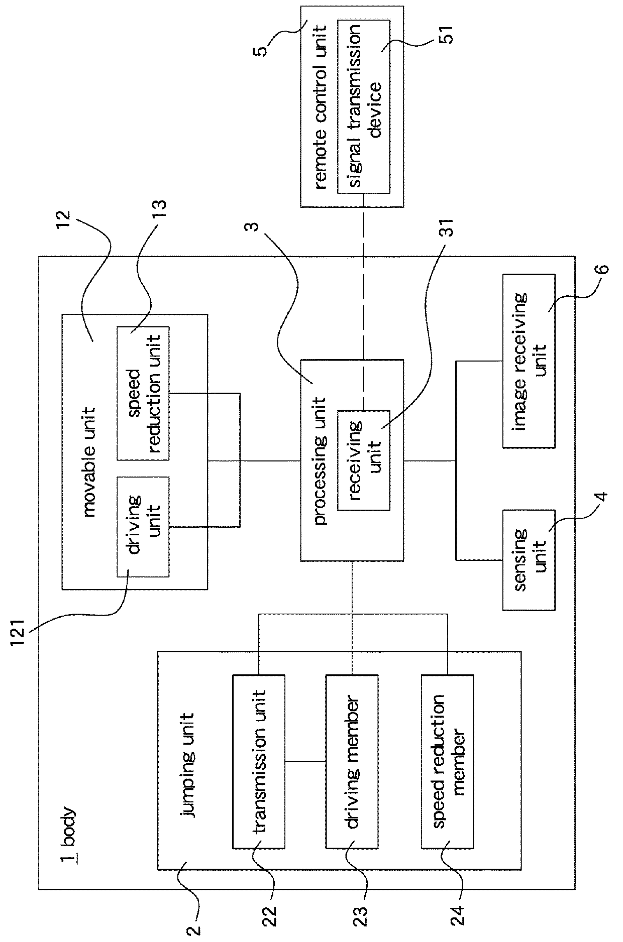
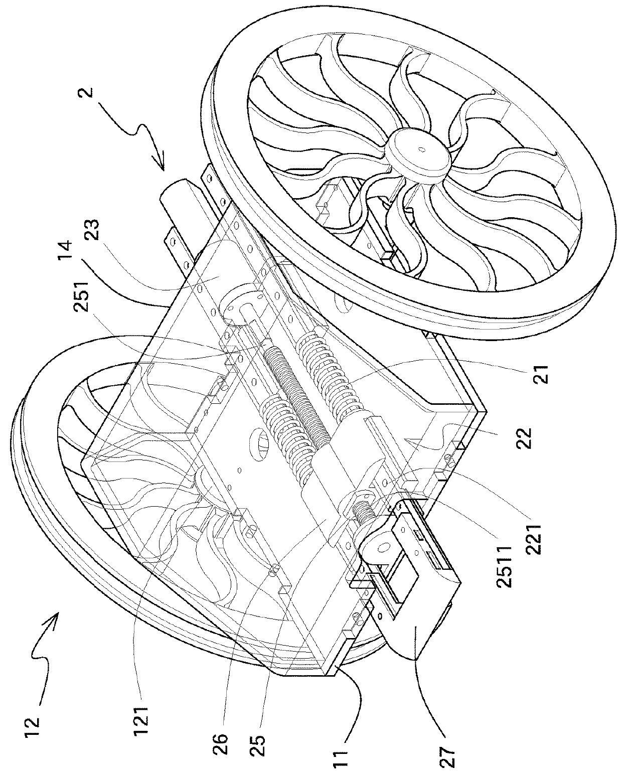
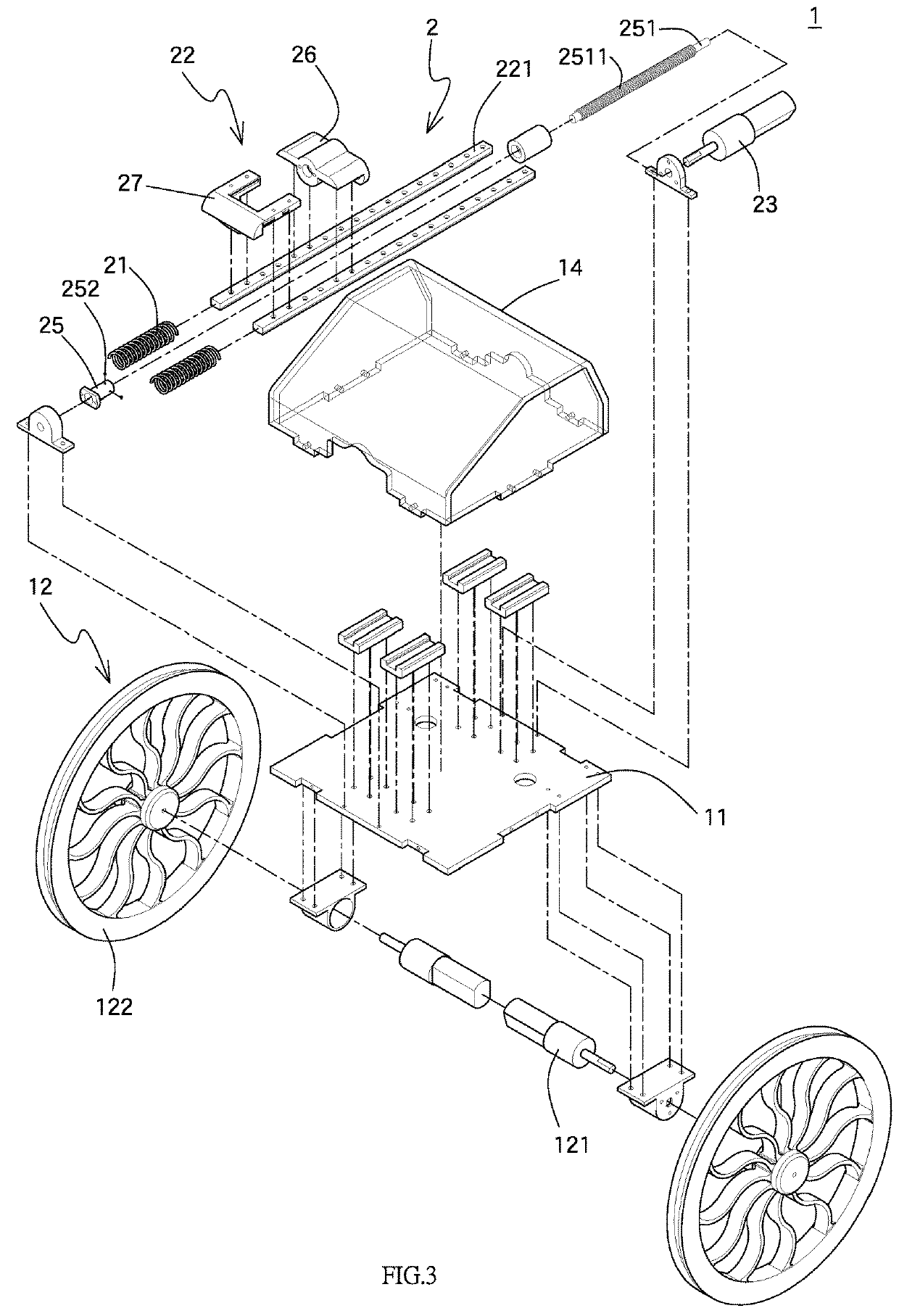
[0025]Referring to FIGS. 1 to 3, the wheeled jumping robot of the present invention comprises a body 1 having a board 11 which is an aluminum board in this embodiment. A movable unit 12 is connected to the body 11 and has a driving unit 121 and two wheels 122, wherein the two wheels 122 are made by plastic and coated with cushion members. The board 11 is located between the two wheels 122. The driving unit 121 is located on a first side of the board 11 and located at inside of each of the two wheels 122. The movable unit 12 has a speed reduction unit 13.

[0026]A jumping unit 2 has two resilient members 21 and a transmission unit 22. The resilient members 21 are compression springs. The transmission unit 22 and the resilient members 21 are respectively connected with a driving member 23 which drives the transmission unit 22 to compress the resilient members 21. The resilient members 21, the transmission unit 22 and the driving member 23 are located on located on the second side of the...


PUM


Abstract

A wheeled jumping robot includes a body with two wheels, and a board is connected between the two wheels. A driving unit and a jumping unit are respectively connected on two sides of the board. The jumping unit has two rails, and a tubular member is located between the two rails and connected to a threaded rod. A bridge is connected between two rails. Rollers are located between a threaded portion of the threaded rod and a tapered contact face of the bridge. When the threaded rod is rotated, the rollers move toward a pre-set position, the bridge compresses resilient members on the two rails. When the tubular member moves toward the pre-set position, the rollers are separated from the threaded rod due to the tapered contact face, the resilient members bounce back. The wheeled jumping robot includes a processing unit for being communicated with a remote control unit.

Description

BACKGROUND OF THE INVENTION1. Fields of the Invention[0001]The present invention relates to a wheeled jumping robot, and more particularly, to a wheeled jumping robot which moves by the wheels and jumps over objects by the jumping unit.2. Descriptions of Related Art[0002]Robots are used in a wide ranges of applications such as military reconnaissance, space exploration, natural disaster assistance, counter terrorism and archeology related actions. Along with the development of auto-control, electronic technology, computer science, artificial intelligence and photo-electric sensing and information processing, the latest robots are capable of proceeding precise actions to meet the requirements in different tasks. It is noted that there are different types of obstacles when the robots move due to the geographical environment, so that the robots are asked to include high operatability and maneuverability. Besides, the robots are also asked to be able to process information at high speed...

Claims


Application Information

Patent Timeline
Patent Type & Authority Applications(United States)
IPC IPC(8): B25J9/16B25J5/00G05D1/00G05D1/02B62D61/00B60K17/22F03G1/00
CPCB25J9/1666A63H11/06B25J9/1697B25J9/162G05D1/0033G05D1/0238G05D1/0242G05D1/0214B62D61/00B60K17/22F03G1/00Y10S901/01Y10S901/47Y10S901/49B25J5/007B60Y2200/47B60K7/0007B60K2007/0038B60K2007/0046B60K2007/0092B62D57/02
Inventor LEE, LIAN-WANGLO, YI-HSUNLYU, YU-FONGCHEN, RUI-PENGHSU, CHUN-CHIH
Owner LUNGHWA UNIVERSITY OF SCIENCE AND TECHNOLOGY
Why Eureka
Try Eureka