Container manufacturing apparatus

a manufacturing device and container technology, applied in the field of container manufacturing devices, can solve the problems of contaminated workplace, low operation speed, ineffective in-mold molding, etc., and achieve the effects of reducing the area consumed for the layout of the container manufacturing device, facilitating and rapid operation, and improving the working environmen

Active Publication Date: 2018-06-28
SHINWOO COSTEC
View PDF8 Cites 3 Cited by
  • Summary
  • Abstract
  • Description
  • Claims
  • Application Information

AI Technical Summary

Benefits of technology

[0106]According to the diverse exemplary embodiments of the present invention, an area consumed for a layout for devices for producing a container may be reduced.
[0107]In particular, molding and heating of a pre-form, container molding and labeling, and container ejection may be performed on one station and movement between modules may be performed via a rotation of a rib plate put on a rotary table and, thus, operations may be advantageously and rapidly performed.
[0108]In particular, according to the present invention, the rotary table may not be moved upward or downward and a rib plate is moved in an up and down direction according to each stage and, thus, all procedures of respective stages may be independently implemented without being affected by a procedure at another stage.
[0109]A working environment and a hygienic condition of a container may be enhanced using an electric machine but not a hydraulic machine.
[0110]In the case of a pre-form molding device, a coupling link is folded and unfolded using a toggle method and, in this regard, in a state in which the coupling link is unfolded, the coupling link provide strong support force to prevent an interval between the pre-form mold, the rib plate, and the second support portion from being increased during injected material injection for molding a pre-form.
[0111]In addition, the pre-form mold and the rib plate are relatively moved in an up and down direction and, thus, a space may be remarkably saved compared with movement in a right and left direction.

Problems solved by technology

However, when in-mold molding according to the prior art is used, since an inject material (hereinafter, referred to as a pre-form) prior to having a shape of a container needs to be molded and container molding and labeling via pre-form heating and pre-form expansion, and container ejection are required, an area occupied by a layout of devices for respective operation stages is very wide and operating speed is very low and, thus, there is a problem in that the in-mold molding is ineffective.
An in-mold molding device according to the prior art is designed as a hydraulic type device and, thus, there is a problem in that a workplace is contaminated due to oil leak, etc. and a container is also contaminated during a manufacture procedure.

Method used


Image

  • Container manufacturing apparatus
  • Container manufacturing apparatus
  • Container manufacturing apparatus

Examples


Embodiment Construction

Technical Object

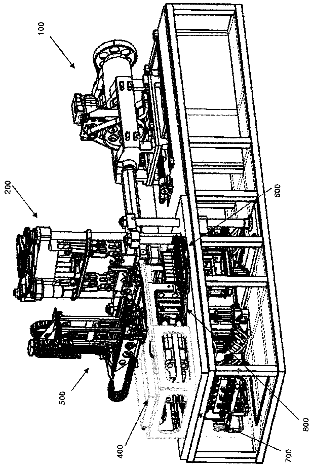
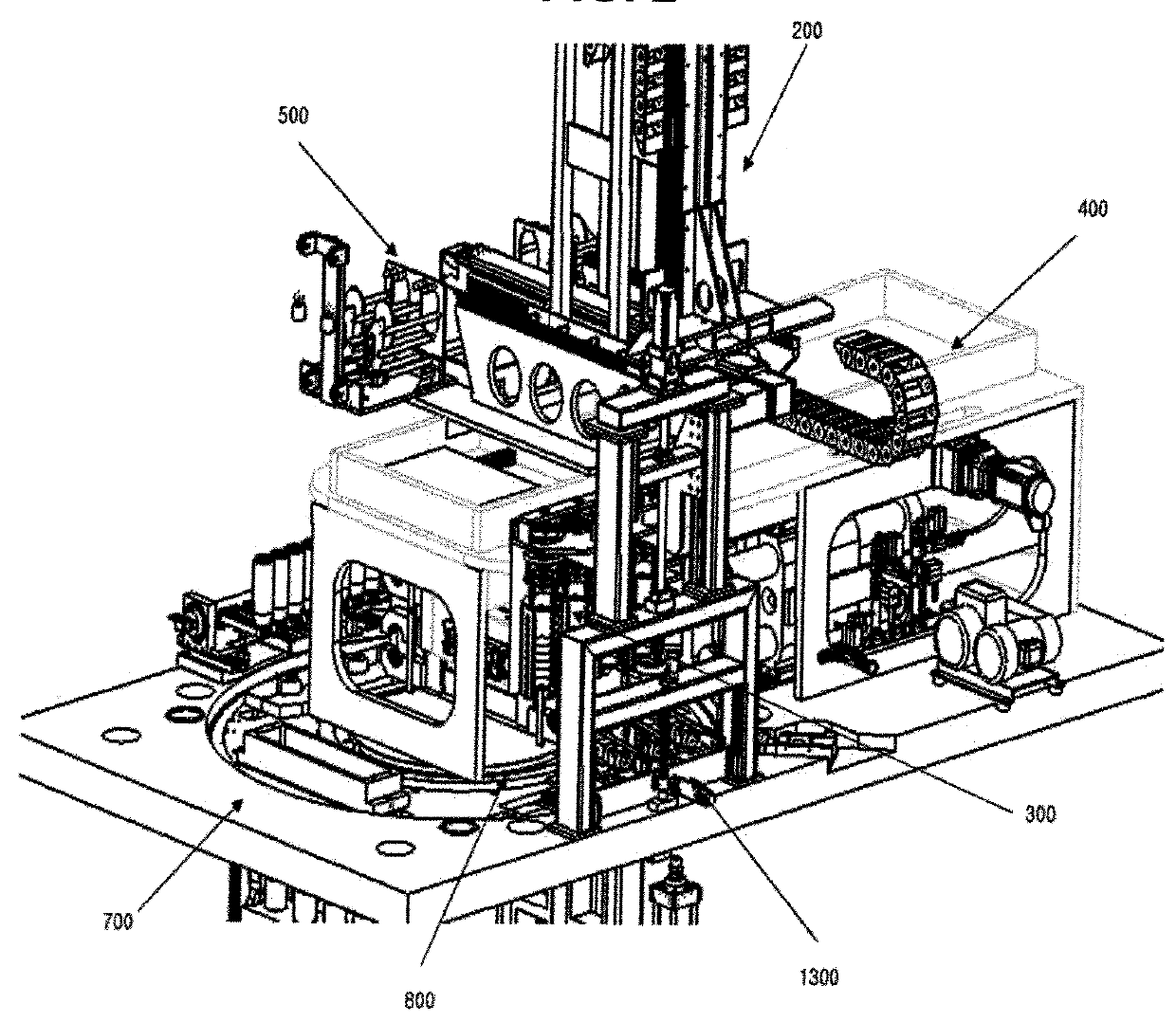
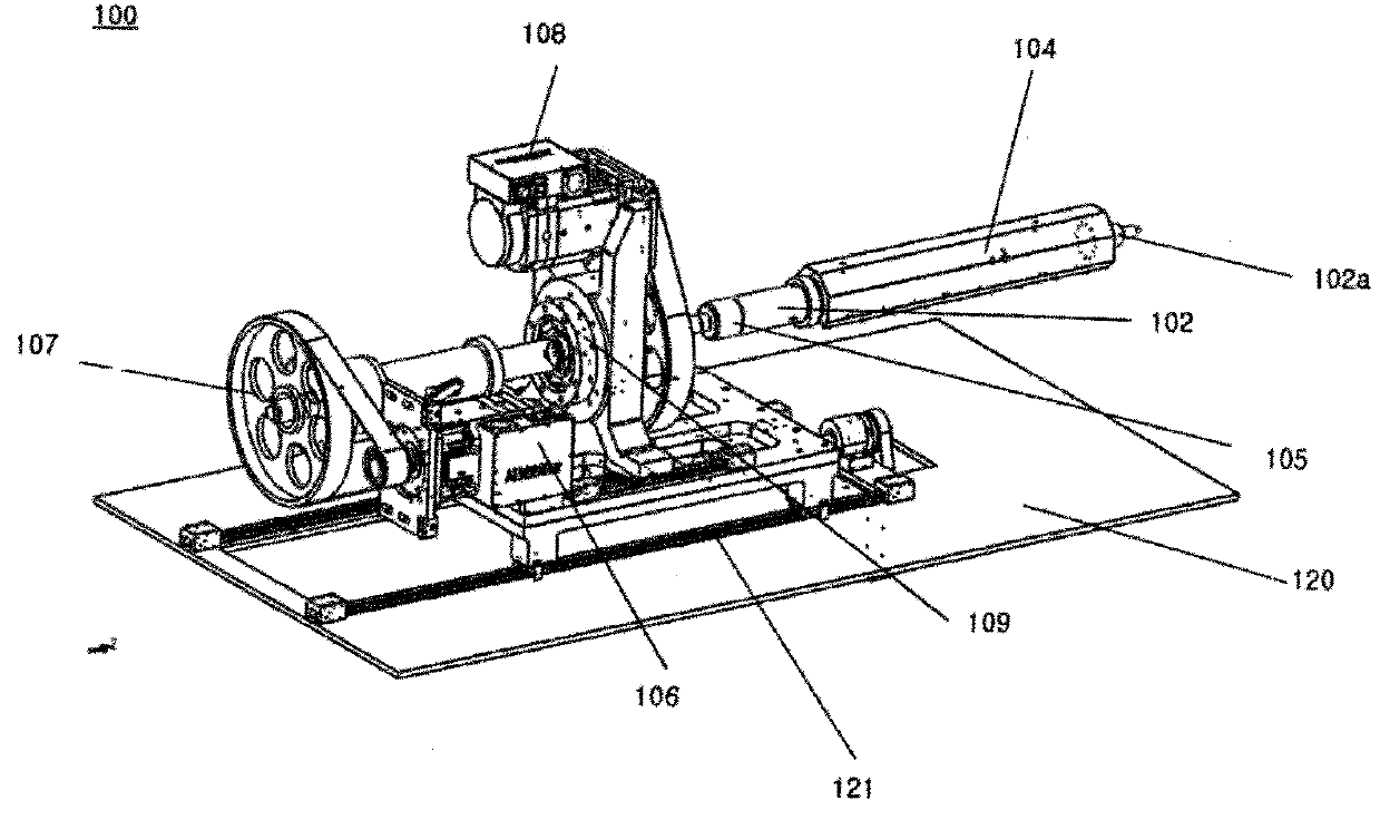
[0008]The present invention provides a container manufacturing device for performing all operation stages for manufacturing a container in one station to enhance workability and to reduce an installation area consumed for a layout of a device.

[0009]In addition, according to the present invention, an operation of a container manufacturing device may be controlled using an electric motor without a hydraulic machine to enhance a working environment and a hygienic condition.

Solution for the Object

[0010]According to an aspect of the present invention, a container manufacturing device includes a pre-form molding module configured to form a shape of a pre-form of a container using a resin material, an injection module connected to the pre-form molding module and configured to supply the resin material to the pre-form molding module, a container molding module configured to inject air to a pre-form completed by the pre-form molding module to expand the pre-form and to form t...


PUM

PropertyMeasurementUnit
driving forceaaaaaaaaaa
poweraaaaaaaaaa
shapeaaaaaaaaaa

Abstract

A container manufacturing device is provided. In detail, the container manufacturing device for performing manufacture of a container pre-form and container molding in a single station via one stop. The container manufacturing device includes a pre-form molding module configured to form a shape of a pre-form of a container using a resin material, an injection module connected to the pre-form molding module and configured to supply the resin material to the pre-form molding module, a container molding module configured to inject air to a pre-form completed by the pre-form molding module to expand the pre-form and to form the shape of the container, and including a container mold, and a rotary table with a rib plate suspended thereon while rotating between the pre-form molding module and the container molding module, the pre-form or the container being mounted on the rib plate.

Description

TECHNICAL FIELD[0001]Apparatuses and methods consistent with the present invention relate to a container manufacturing device, and more particularly, a label container manufacturing device for performing container pre-form manufacture and heating, in-mold labeling, container molding, and container ejection in a single station.BACKGROUND ART[0002]Many devices for attaching a label with an embellishment, trade name, explanation, etc. printed thereon have been widely used to indicate an embellishment, a trade name, or an explanation on a surface of a blow molding container formed of a synthetic resin.[0003]One of methods of attaching a label is an in-mold molding method of pre-putting an in-mold molding label (hereinafter, referred to as a label) on a mold and simultaneously attaching the label to a surface of a surrounding wall of a main body of a container while molding the main body of the container.[0004]In the in-mold molding method, a label is simultaneously attached while a main...

Claims


Application Information

Patent Timeline
Patent Type & Authority Applications(United States)
IPC IPC(8): B29C49/06B29C49/78B29C49/24B29C49/36B29C49/64B29C49/70
CPCB29C49/062B29C49/786B29C49/24B29C49/36B29C49/6409B29C49/70B29C2049/2412B29C2949/78151B29C2949/78386B29C2949/78663B29L2031/7158B29C49/063B29C49/2408B29C49/42B29C49/4278B29C49/64B29C49/42069B29C49/06B29C49/62B65D1/02B29C49/4236B29C49/4252B29C49/56B29C49/6463B29C2049/563B29C2049/566B29C2793/0081B29C49/42105B29C49/78B29C49/28006B29C49/42073B29C49/42101B29C49/42362B29C2049/023B29C49/5603B29C2049/5664B29C2049/7861B29C2049/78675
Inventor BYUN, WOO HONG
Owner SHINWOO COSTEC
Why Eureka
Try Eureka