Dc-dc converter

a converter and converter technology, applied in the direction of electric variable regulation, process and machine control, instruments, etc., can solve the problems of reducing efficiency when performing zvs, and achieve the effects of suppressing an increase in reactive current, widening the range of zvs operation, and high efficiency

Active Publication Date: 2018-06-28
MURATA MFG CO LTD
View PDF13 Cites 7 Cited by
  • Summary
  • Abstract
  • Description
  • Claims
  • Application Information

AI Technical Summary

Benefits of technology

[0015]With this configuration, the detection of load current enables determination of whether the load is lightly loaded or heavily loaded and appropriate switching between the full-bridge operation mode and the half-bridge operation mode in accordance with the result of the determination enables the switching control to be performed with high efficiency in a wide load area.
[0016]According

Problems solved by technology

However, since the ZVS range is restricted and reactive current is increased in proportion to the difference between a

Method used


Image

  • Dc-dc converter
  • Dc-dc converter
  • Dc-dc converter

Examples


Embodiment Construction

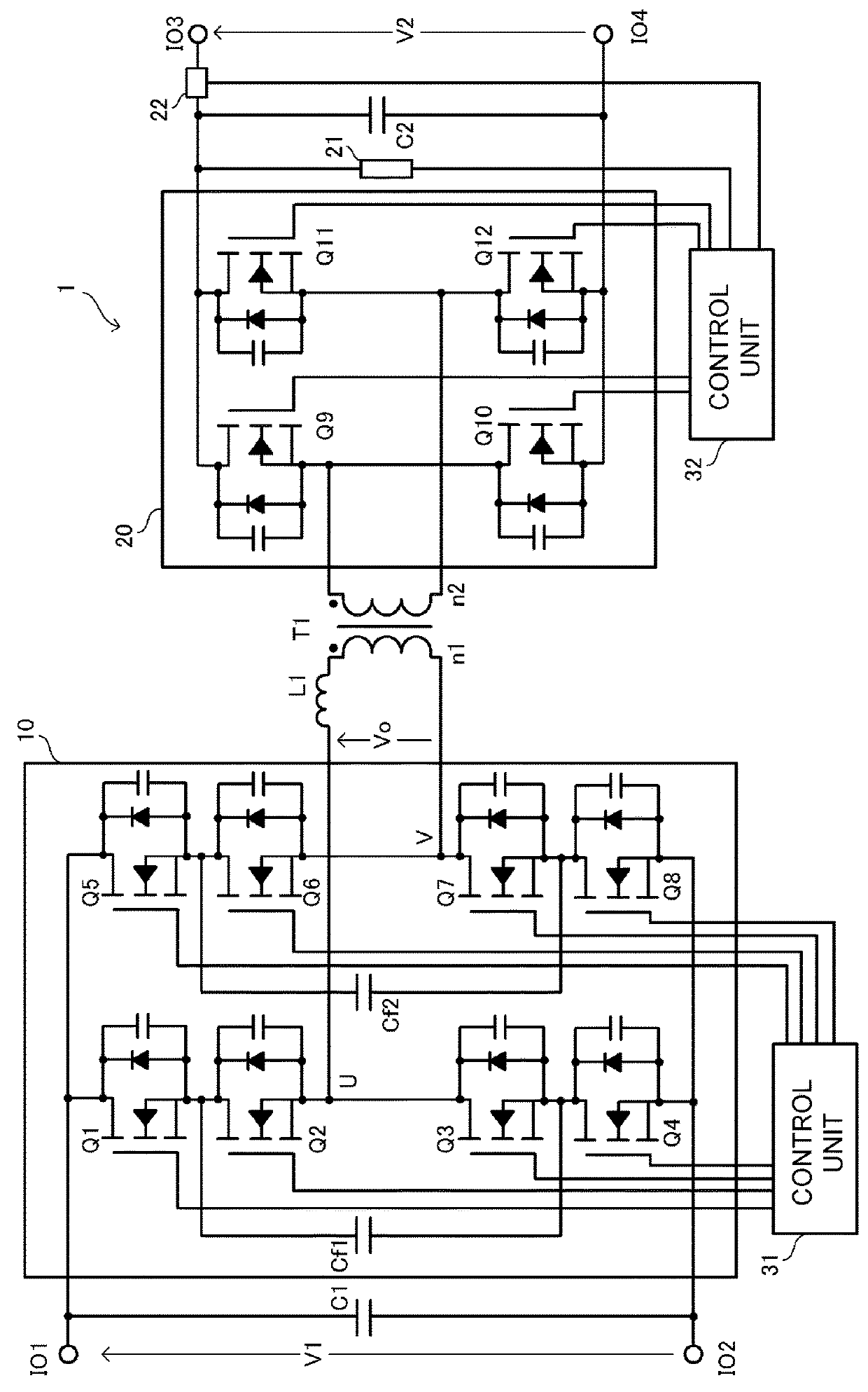
[0030]An exemplary DC-DC converter described below is a DAB DC-DC converter including two full-bridge circuits. In the DAB DC-DC converter, the two full-bridge circuits are set so as to have the same driving frequency and are controlled so as to have a phase difference to transmit electric power between the two full-bridge circuits.

[0031]FIG. 1 is a circuit diagram of a DC-DC converter 1 according to an exemplary embodiment.

[0032]As shown, the DC-DC converter 1 has input-output terminals IO1, IO2, IO3, and IO4. A load and a direct-current power supply are connected to the input-output terminals IO1, IO2, IO3, and IO4. The DC-DC converter 1 is a bi-directional DC-DC converter that transforms direct-current voltage supplied from the input-output terminals IO1 and IO2 or the input-output terminals IO3 and IO4 and outputs the transformed voltage from the remaining input-output terminals.

[0033]For purposes to the disclosure, the input-output terminals IO1 and IO2 correspond to an “input ...


PUM


Abstract

A DC-DC converter includes a full-bridge circuit connected to a primary winding of a transformer and a full-bridge circuit connected to a secondary winding of the transformer. The full-bridge circuit includes a first series circuit including a first set of switching elements, a second series circuit including a second set of switching elements, a first charge-discharge capacitor connected to a node between a first pair of the first switching elements and a node between a second pair of first switching elements, and a second charge-discharge capacitor connected to a node between the a first pair of the second switching elements and a node between a second pair of the second switching elements. The full-bridge circuit can operate in one of a full-bridge operation mode and a half-bridge operation mode. The disclosed DC-DC converter can constantly operate with high efficiency even when the variation range of a load is wide.

Description

CROSS-REFERENCE TO RELATED APPLICATIONS[0001]The present application is a continuation of PCT / JP2016 / 071485 filed Jul. 22, 2016, which claims priority to Japanese Patent Application No. 2015-169417, filed Aug. 28, 2015, the entire contents of each of which are incorporated herein by reference.TECHNICAL FIELD[0002]The present disclosure relates to a dual active bridge (DAB) direct current-to-direct current (DC-DC) converter.BACKGROUND[0003]Patent Document 1 (identified below) discloses an existing DAB converter. In the DAB converter described in Patent Document 1, a full-bridge circuit is connected to each of a primary winding and a secondary winding of a transformer and the switching phase difference between the two full-bridge circuits is appropriately controlled to perform transfer of power.[0004]Patent Document 1: U.S. Pat. No. 5,355,294.[0005]With the converter described in Patent Document 1, switching loss can be reduced by performing zero voltage switching (ZVS) using leakage ...

Claims


Application Information

Patent Timeline
IPC IPC(8): H02M3/335H02M1/32H02M3/07
CPCH02M3/33584H02M1/32H02M3/07Y02B70/10H02M1/0032H02M1/0058
Inventor ITOH, JUNICHIHIGA, HAYATO
Owner MURATA MFG CO LTD
Why Eureka
Try Eureka