N-way star configuration power amplifier with peaking amplifier impedance inverters

a technology of impedance inverters and power amplifiers, which is applied in the direction of rf amplifiers, two-way amplifiers, high frequency amplifiers, etc., can solve the problems that conventional doherty amplifiers may not be able to meet performance requirements, and achieve the effect of improving efficiency n-way, high power outputs, and high impedan

Inactive Publication Date: 2018-06-28
MACOM TECH SOLUTIONS HLDG INC
View PDF1 Cites 13 Cited by
  • Summary
  • Abstract
  • Description
  • Claims
  • Application Information

AI Technical Summary

Benefits of technology

[0005]Methods and structures for improved efficiency N-way amplifiers are described. An N-way amplifier (which may also be referred to as a multi-way amplifier) can comprise at least two amplifiers arranged to amplify, in parallel, at least two signals derived from an input signal to the N-way amplifier. By amplifying portions of a received signal in parallel, high power outputs can be obtained with a multi-way amplifier. According to some embodiments, impedance inverters are added to the output(s) of one or more peaking amplifiers that are arranged in parallel with a main amplifier. The impedance inverters can be engineered to present a desired impedance to the peaking amplifier(s) at full power operation of a multi-way amplifier. The desired impedance can be an impedance that matches a low-impedance value at an output of the main amplifier. When the peaking amplifiers are in a power back-off state, a higher impedance is presented to the main amplifier, which can improve output power back-off efficiency to values greater than 60%. A multi-way amplifier configuration having impedance inverters connected to outputs of the peaking amplifier(s) can enable broadband, high-power amplification. Additionally, the characteristic impedance of the inverters can be changed to accommodate one or more additional peaking amplifiers for higher-order multi-way amplifiers.

Problems solved by technology

In some cases, conventional Doherty amplifiers may not be able to satisfy performance requirements for proposed communication standards.

Method used


Image

  • N-way star configuration power amplifier with peaking amplifier impedance inverters
  • N-way star configuration power amplifier with peaking amplifier impedance inverters
  • N-way star configuration power amplifier with peaking amplifier impedance inverters

Examples


Embodiment Construction

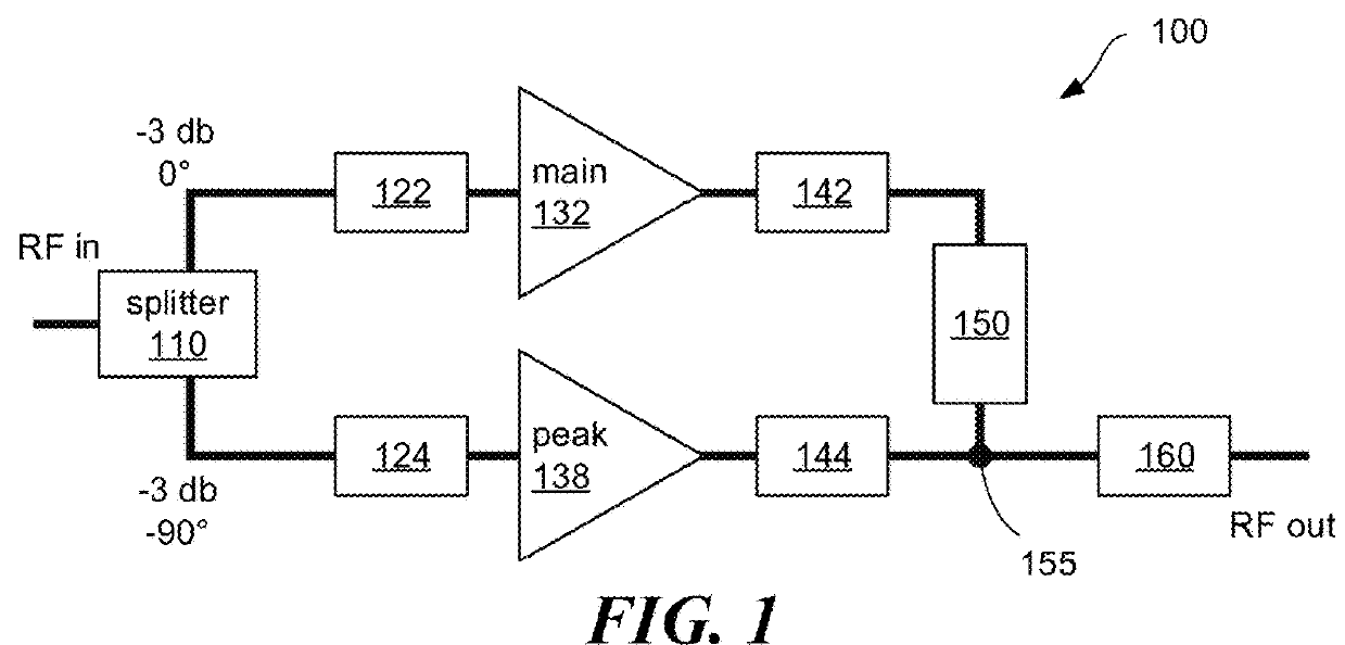
[0023]One approach to amplifying signals for communications is to use a Doherty amplifier, an example of which is depicted schematically in FIG. 1. To aid in understanding the present technology, a brief summary of Doherty amplification is provided.

[0024]A Doherty amplifier 100 can comprise a 90-degree power splitter 110, which divides a received RF signal into two output signal paths that connect to a main amplifier 132 and a peaking amplifier 138. The main amplifier 132 and peaking amplifier 138 are arranged on parallel circuit branches. The power splitter 110 can also delay (by approximately 90 degrees) the phase of the signal provided to the peaking amplifier with respect to the phase of the signal provided to the main amplifier, as indicated in FIG. 1. Two signals, derived from the RF input signal, can be amplified in parallel by the main amplifier 132 and peaking amplifier 138.

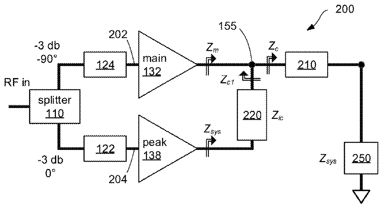
[0025]Impedance-matching components 122, 124 can be placed before the main amplifier 132 and peaking ...


PUM


Abstract

Multi-way amplifiers having impedance inverters connected to outputs of one or more peaking amplifiers are described. The output of the main amplifier may connect directly to a combining node and output impedance matching network. The multi-way amplifier configuration can improve efficiency at power back-off and improve RF bandwidth.

Description

CROSS-REFERENCE TO RELATED APPLICATION[0001]This Application claims priority under 35 U.S.C. § 119(e) to U.S. Provisional Application Ser. No. 62 / 438,774, entitled “N-WAY STAR CONFIGURATION DOHERTY POWER AMPLIFIER WITH PEAKING AMPLIFIER IMPEDANCE INVERTERS”, filed on Dec. 23, 2016, which is incorporated herein by reference in its entirety.BACKGROUNDTechnical Field[0002]The technology relates to multi-way amplifiers.Discussion of the Related Art[0003]High-speed power amplifiers formed from semiconductor materials have a variety of useful applications, such as radio-frequency (RF) communications, radar, RF energy, and microwave applications. Gallium nitride semiconductor material has received appreciable attention in recent years because of its desirable electronic and electro-optical properties. GaN has a wide, direct bandgap of about 3.4 eV that corresponds to the blue wavelength region of the visible spectrum. Because of its wide bandgap, GaN is more resistant to avalanche breakdow...

Claims


Application Information

Patent Timeline
Patent Type & Authority Applications(United States)
IPC IPC(8): H03F1/02H03F1/56H03F3/62H03F3/195
CPCH03F1/0288H03F1/56H03F3/62H03F3/195H03F2200/387H03F2200/451H03F3/19H03F3/602
Inventor PHAM, BI NGOC
Owner MACOM TECH SOLUTIONS HLDG INC
Why Eureka
Try Eureka