Method for Manufacturing a Wind Turbine Rotor Blade Root Section with Pultruded Rods and Associated Wind Turbine Blade

Active Publication Date: 2018-07-05
GENERAL ELECTRIC CO
View PDF6 Cites 1 Cited by
  • Summary
  • Abstract
  • Description
  • Claims
  • Application Information

AI Technical Summary

Benefits of technology

The patent text is discussing ways to strengthen the root of a structure in the directions where it is stretched. One method is to add some off-center fibers to the root section. This may be done by putting layers of fabric with these fibers in place between the cartridges and compacting them to make them thinner. The fabric helps to reinforce the root and make it stronger.

Problems solved by technology

Such increases in rotor blade size, however, may impose increased loads on various wind turbine components.
For example, larger rotor blades may experience increased stresses at the connection between the blade root and the hub, leading to challenging design constraints, both characterized by extreme events and fatigue life requirements.
No. 2013 / 0111752 describes a problem with conventional wind turbine blades made of fiber reinforced plastic wherein the prevailing reinforcement fibers run in a longitudinal direction of the rotor blade, resulting in an “ovalization” of the root (also called root ring) once the blade is removed from the molding tool and is subjected to gravity forces without support at the root end.

Method used


Image

  • Method for Manufacturing a Wind Turbine Rotor Blade Root Section with Pultruded Rods and Associated Wind Turbine Blade
  • Method for Manufacturing a Wind Turbine Rotor Blade Root Section with Pultruded Rods and Associated Wind Turbine Blade
  • Method for Manufacturing a Wind Turbine Rotor Blade Root Section with Pultruded Rods and Associated Wind Turbine Blade

Examples


Embodiment Construction

[0034]Reference now will be made in detail to embodiments of the invention, one or more examples of which are illustrated in the drawings. Each example is provided by way of explanation of the invention, not limitation of the invention. In fact, it will be apparent to those skilled in the art that various modifications and variations can be made in the present invention without departing from the scope or spirit of the invention. For instance, features illustrated or described as part of one embodiment can be used with another embodiment to yield a still further embodiment. Thus, it is intended that the present invention covers such modifications and variations as come within the scope of the appended claims and their equivalents.

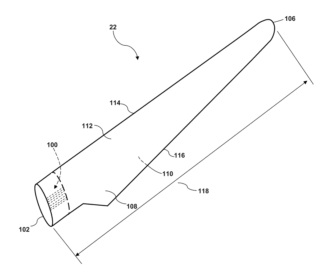
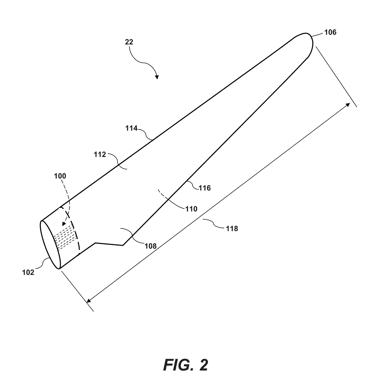
[0035]The present invention relates to a unique blade root section (and method of making such blade root section), wherein the root section exhibits improved strength and structural properties and can be manufactured in a fast and efficient automated manner...


PUM

PropertyMeasurementUnit
Lengthaaaaaaaaaa
Centrifugal forceaaaaaaaaaa
Diameteraaaaaaaaaa

Abstract

A method for manufacturing a root section of a wind turbine blade includes assembling a mold having an inner cylinder segment, an outer cylinder segment, and a bottom flange, wherein a radial space is defined between the inner and outer cylinders. Root hub connectors are attached circumferentially around the bottom flange so that the root hub connectors extend axially into the radial space. A first cartridge of pultruded rods is loaded into the space, wherein the first cartridge includes a plurality of first pultruded rods arranged adjacent to the inner cylinder segment. The space is sealed, for example with a lid or top flange, and the space is evacuated. A resin is infused into the space so that the resin migrates through the radial space between the pultruded rods, and is then cured. The root section is then removed from the mold. A wind turbine blade root section formed by the method is encompassed by the invention.

Description

FIELD OF THE INVENTION[0001]The present subject matter relates generally to wind turbines and, more particularly, to a root configuration of a wind turbine rotor blade assembly.BACKGROUND OF THE INVENTION[0002]Wind power is considered one of the cleanest, most environmentally friendly energy sources presently available, and wind turbines have gained increased attention in this regard. A modern wind turbine typically includes a tower, generator, gearbox, nacelle, and a rotor. The rotor is coupled to the nacelle and includes a rotatable hub having one or more rotor blades. The rotor blades are connected to the hub by a blade root. The rotor blades capture kinetic energy from wind using known airfoil principles and convert the kinetic energy into mechanical energy through rotational energy to turn a shaft coupling the rotor blades to a gearbox, or if a gearbox is not used, directly to the generator. The generator then converts the mechanical energy to electrical energy that may be depl...

Claims


Application Information

Patent Timeline
IPC IPC(8): F03D1/06
CPCF03D1/0675F05B2230/21F05B2240/30F05B2220/30B29C70/541B29C70/42F03D1/0658B29L2031/085B29C39/08B29C39/26B29C70/48B29D99/0028Y02E10/72Y02P70/50
Inventor ALBERT, BENSELYHYNUM, DANIEL ALANRIAHI, AMIR
Owner GENERAL ELECTRIC CO
Why Eureka
Try Eureka